

A practical guide to designing CNC machined parts with accessible geometry, stable walls, realistic tolerances and fewer expensive setups—without compromising the features that make the part work.
Start with function—then make that intent easy to cut and inspect.
CNC machining is flexible, but every face still needs a tool approach, a rigid setup and a measurable acceptance condition. Cost rises when geometry forces long tools, repeated repositioning, slow finishing or inspection that cannot reach the feature.
A strong DFM review begins by identifying the datums, fits, sealing faces and alignment features that actually control the assembly. Those relationships should remain easy to locate, machine and inspect. Material that does not serve load, stiffness, heat transfer or assembly can then be simplified without weakening the design intent.
The 3D model and drawing play different roles. The model defines nominal geometry; the drawing communicates tolerances, threads, surface condition, finishing and inspection requirements. Sending both gives the manufacturing engineer enough context to choose a setup instead of guessing which dimensions matter most.
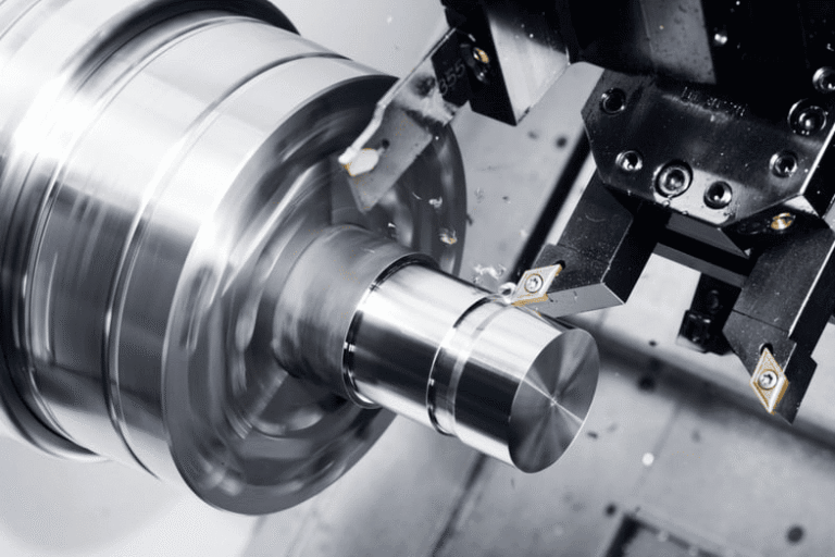
Internal radii determine the cutter—and the cutter determines the risk.
A rotating end mill always leaves an internal radius. When the specified corner nearly matches the cutter radius, tool engagement spikes and the machine must slow down. Providing a radius larger than the cutter creates room for a smoother toolpath and a more consistent finish.
Pocket depth compounds the problem because deeper features require longer tools. A long cutter is less rigid, more prone to vibration and less effective at clearing chips. Keeping pocket depth near four times the cutter diameter is a useful early design target, although the final limit depends on material, wall geometry, tool access and finish requirements.
As a practical starting point, an internal corner radius around one third of the pocket depth leaves more options for robust tooling. This is guidance rather than a universal rule. If a mating component truly needs a square corner, localized relief may be more economical than forcing every surface to be cut with a very small tool.
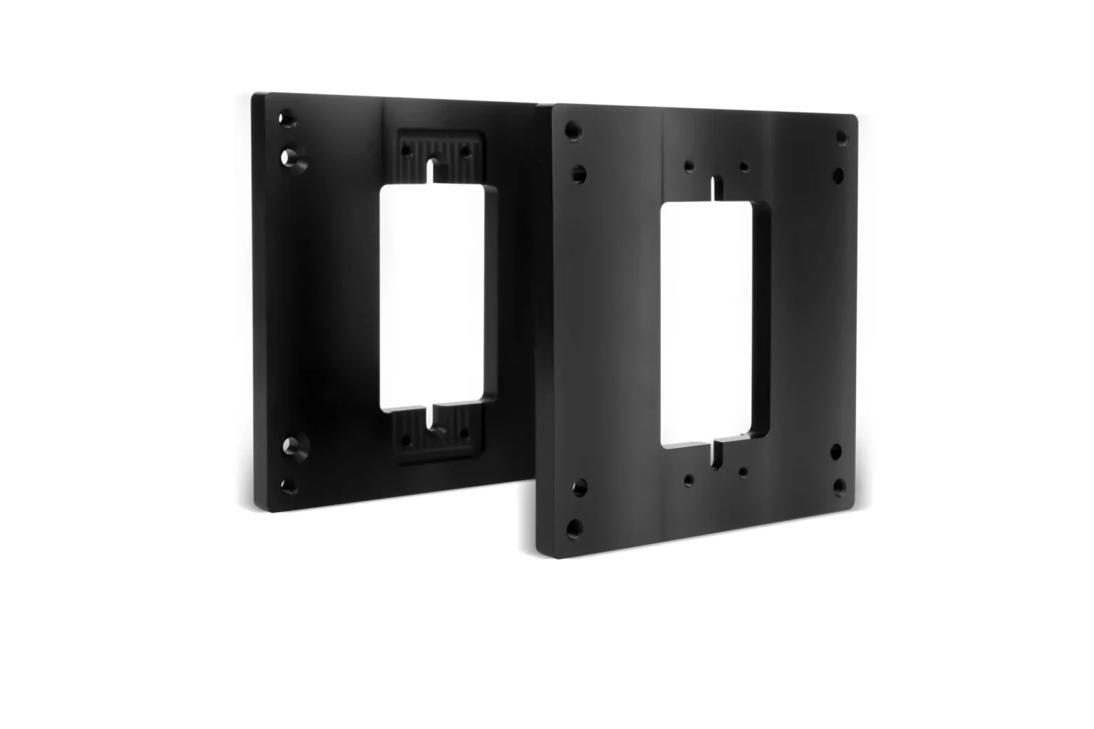
Give thin walls and small details enough stiffness to survive cutting forces.
Walls move under tool pressure, heat and clamping. As a wall becomes taller or thinner, it can vibrate during machining and relax after the fixture is released. The result may be chatter marks, taper or dimensions that change when the part is unclamped.
Wall thickness therefore needs to be considered together with unsupported height, material stiffness and cutting direction. A rib or return can add useful rigidity, provided it does not block the cutter. Deep narrow slots create the opposite condition: they demand a small, long-reach tool precisely where the geometry offers the least support.
Plastics deserve a separate review from metals. They respond more strongly to clamping pressure and temperature, and their dimensions can continue to change with moisture or stress relaxation. A metal-like thin-wall rule applied without considering the polymer grade can produce a part that measures correctly in the fixture but moves later.
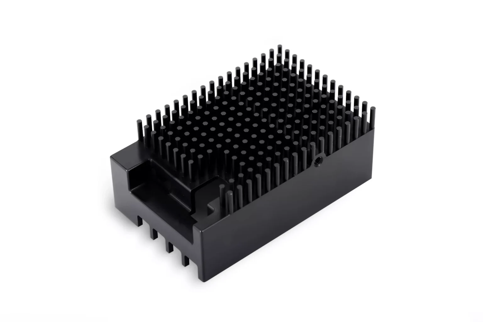
Minimum wall thickness depends on stiffness, heat and how the stock was made.
A single minimum wall value hides the largest source of variation: material behavior. The table below is a conservative RFQ-stage starting point for unsupported machined walls, not a guaranteed process limit. Short walls with excellent access can go thinner; tall walls, interrupted cuts, tight flatness or poor clamping access often need more material.
Protolabs identifies features at or below 0.51 mm as thin-wall geometry and publishes a nominal part thickness of 1.02 mm for its automated process. Mockup uses the more conservative ranges below for early design review because they account for material family and leave room for fixture and geometry effects.
| Material family | Preferred starting wall | Height / thickness target | Main risk |
|---|---|---|---|
| Aluminum 6061 / 7075 | 0.8–1.0 mm | ≤ 6:1 | Chatter and local distortion |
| Mild / tool steel | 1.0–1.2 mm | ≤ 5:1 | Cutting force and residual stress |
| Stainless steel | 1.2–1.5 mm | ≤ 4:1 | Work hardening and heat |
| Titanium | 1.2–1.5 mm | ≤ 4:1 | Heat concentration and spring-back |
| Brass / copper | 0.8–1.2 mm | ≤ 5:1 | Burring; copper can smear |
| POM / ABS | 1.5–2.0 mm | ≤ 4:1 | Clamping, heat and creep |
| Nylon | 2.0–2.5 mm | ≤ 3:1 | Moisture movement and flexibility |
| PEEK / polycarbonate | 1.5–2.0 mm | ≤ 4:1 | Residual stress and heat |
Use standard tools and leave room for the tool to finish the feature.
Standard drill sizes, thread forms and readily available reamers reduce special tooling and simplify inspection. The drawing should distinguish an ordinary clearance hole from a precision bore, because the manufacturing and measurement routes are not the same.
Blind holes need additional depth for the drill point and chip clearance. Thread depth should be stated separately from drilled depth, while a suitable runout or relief gives the threading tool space to finish. Holes placed too close to an edge can break through into a thin wall and distort it; intersecting holes can leave internal burrs that are difficult to reach.
Threads in aluminum or plastic may be adequate for light assembly, but repeated service can wear the base material. When the joint will be opened often or carries sustained load, a threaded insert may provide a more durable interface. That decision should be based on assembly duty rather than applied to every hole by default.
Depth-to-diameter ratio changes the drilling strategy.
Ordinary drills evacuate chips efficiently only while coolant and flute space remain effective. Once depth increases, pecking, through-tool coolant, pilot drilling or specialized tooling may be needed. The ratios below are useful for deciding when a hole should receive explicit manufacturing review.
| Feature | Preferred range | Review threshold | Design implication |
|---|---|---|---|
| Standard drilled hole | ≤ 3×D | > 5×D | Chip evacuation becomes important |
| Deep drilled hole | 5–10×D | > 10×D | Special tooling and runout control |
| Reamed precision bore | ≤ 5×D | > 5×D | Pilot straightness controls result |
| Blind tapped thread | 1–1.5×D engagement | > 2×D engagement | Extra thread rarely adds strength |
| Threaded insert | Per insert specification | Thin surrounding wall | Boss diameter and installation access |
Tight tolerances create a chain of manufacturing and inspection consequences.
A tighter tolerance can require a more stable fixture, slower finishing pass, temperature control and a more capable measurement method. Applied across an entire drawing, those consequences accumulate even when many dimensions have no meaningful effect on function.
A clear datum structure is often more valuable than a blanket tolerance because it tells manufacturing and inspection how the part is established in the assembly. Fits and GD&T can then control alignment, sealing, motion or location directly, without creating a long stack of tightly toleranced coordinate dimensions.
Surface roughness should follow the same logic. A sealing face, bearing surface or optical interface may need a controlled finish; a hidden clearance surface often does not. Before releasing an unusually tight requirement, confirm that the selected inspection method can reach the feature and make the intended decision with suitable confidence.
| Nominal dimension | General tolerance |
|---|---|
| 0.5–3 mm | ±0.10 mm |
| >3–6 mm | ±0.10 mm |
| >6–30 mm | ±0.20 mm |
| >30–120 mm | ±0.30 mm |
| >120–400 mm | ±0.50 mm |
| >400–1000 mm | ±0.80 mm |
| >1000–2000 mm | ±1.20 mm |
Five-axis machining improves access, but it does not remove tool and fixture constraints.
Five-axis motion lets the tool approach compound angles and contoured surfaces while reducing datum transfers. Its main design value is often a shorter, more rigid tool or the ability to keep several critical faces in one setup—not complexity for its own sake.
The spindle, holder and machine head still need collision clearance. A surface that the tool tip can theoretically touch may remain unreachable once the holder diameter and neighboring walls are considered. Deep cavities should open away from the part, and adjacent bosses should leave enough angular space for the tool to tilt.
Simultaneous five-axis finishing also creates a surface-direction question. Tool contact changes continuously, so scallop height, lead angle and transitions between toolpaths affect appearance. If a contoured face is cosmetic, sealing or aerodynamic, define the acceptable surface result rather than assuming five-axis automatically means a flawless finish.
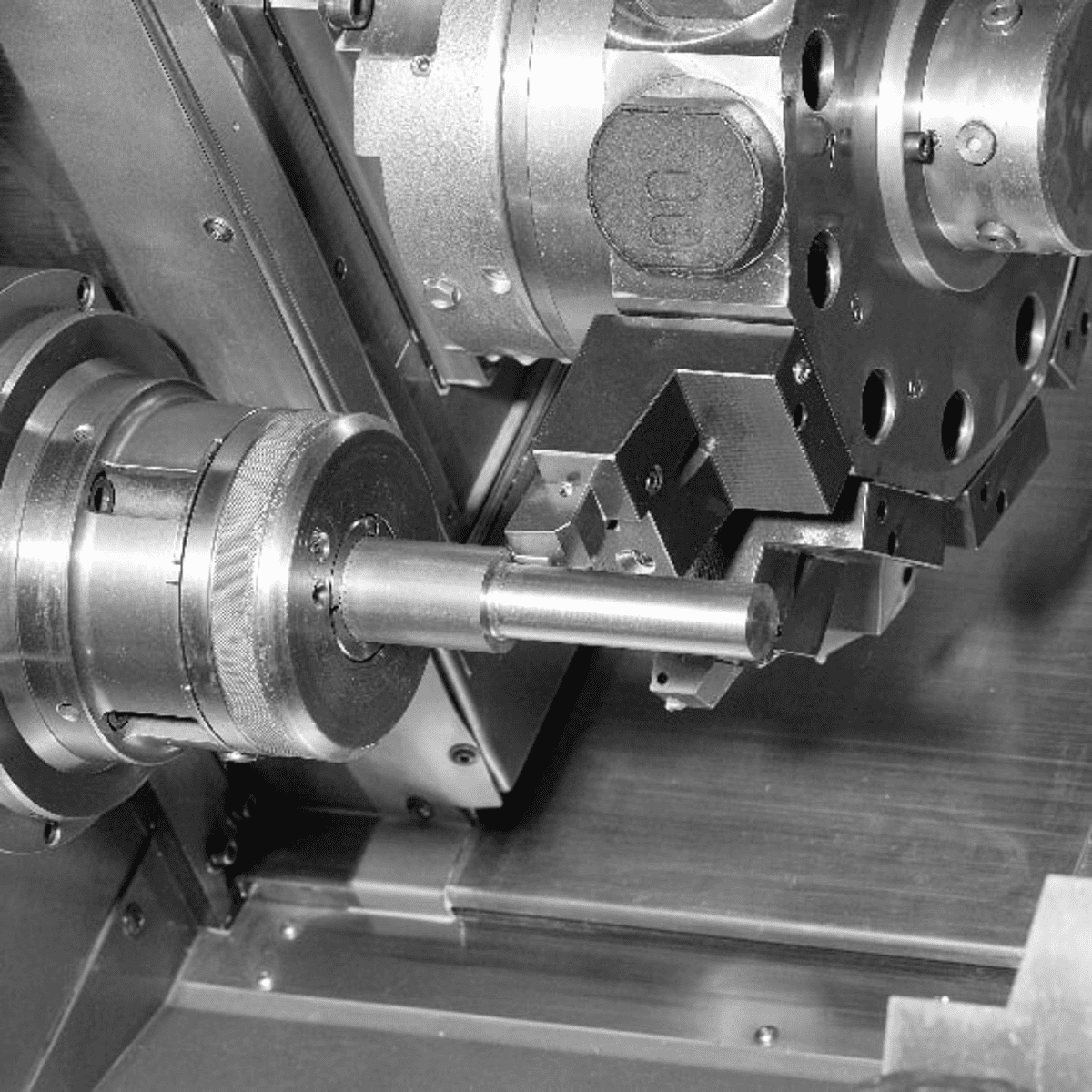
| Geometry | 3-axis / 3+2 consequence | 5-axis opportunity | Remaining constraint |
|---|---|---|---|
| Features on 5 faces | Multiple setups | One controlled setup | Workholding still blocks one face |
| Compound-angle bores | Custom fixture or indexing | Direct tool alignment | Holder clearance around entry |
| Deep drafted wall | Long tool | Tilted shorter tool | Head and shank collision |
| Freeform surface | Ball-end raster path | Continuous orientation | Scallop and blend control |
| Undercut | Special tool | Limited tilted access | True enclosed undercuts remain inaccessible |
Control a bearing bore from the surfaces that locate it in the assembly.
Consider a gearbox housing that bolts to a base and carries a bearing bore. The functional requirement is not merely the bore diameter: the bearing axis must sit at the correct height and orientation relative to the mounting interface, while the flange locates laterally against a mating shoulder.
A practical datum scheme can establish the mounting plane as datum A, the lateral locating face as datum B and a dowel hole or end face as datum C. The bore size receives its fit tolerance. Its axis can then receive a position tolerance relative to A, B and C, while perpendicularity or parallelism is added only if position alone does not fully protect the bearing alignment.
This approach is clearer than applying tight plus/minus coordinates to the bore center from several unrelated edges. It also gives inspection a reproducible setup: simulate A, align B, clock from C, then evaluate the bore axis. The exact tolerance value must come from bearing clearance, shaft alignment, housing stiffness and assembly analysis—not from a generic machining capability.
| Functional need | Drawing control | Datum reference | Likely verification |
|---|---|---|---|
| Housing sits without rocking | Flatness of mounting plane | Datum feature A | Surface plate or CMM |
| Flange locates laterally | Profile / perpendicularity as needed | A | B | CMM or height method |
| Bearing fits correctly | Bore size tolerance | Size feature | Bore gauge / CMM |
| Bearing axis is located | Position of bore axis | A | B | C | CMM axis evaluation |
| Shaft remains aligned | Orientation within position or separate control | A | B | CMM / functional gauge |
Design the complete process—not only the as-machined shape.
Features on opposite faces can force additional setups and datum transfers. Each repositioning introduces more fixturing, handling and opportunity for relationship error. Where practical, critical features should share an accessible orientation, while the part retains a stable surface or sacrificial stock for clamping.
Finishing adds another layer to the dimensional plan. Anodizing, plating and coating can change fits, threads and edge condition; passivation and cosmetic treatments impose their own preparation and acceptance requirements. Electrical contacts, sealing faces and precision interfaces may need masking or a deliberate machining allowance.
Cosmetic zones should be identified before production so fixture or rack locations do not land on a visible surface. The drawing should also state whether dimensions apply before or after finishing. Without that distinction, a correct machined part can become an incorrect finished part—or inspection can reject a feature at the wrong stage.
Guidance connected to real manufacturing decisions.
Mockup helps product teams move from CAD review and DFM through manufacturing, inspection and repeat production. Our engineering guides translate that operating experience into practical decisions you can apply before requesting a quote.
Questions from engineering teams.
What is a good internal corner radius?+
Use the largest radius the design allows. A radius slightly larger than the selected cutter radius reduces engagement and improves finish; a pocket corner radius around one third of pocket depth is a useful early guideline, not a universal rule.
How deep should a CNC pocket be?+
Shallower is generally more stable and economical. Keeping depth near four times cutter diameter or less is a useful starting point, while deeper features need review for tool reach, chip evacuation, wall stiffness and finish.
What is a standard CNC tolerance?+
General tolerances may follow ISO 2768 or a supplier standard, but the released drawing controls. Feature-specific tolerances should come from functional fits, datum relationships and a suitable inspection method.
Should every CNC dimension be tightly toleranced?+
No. Blanket tight tolerances increase machining and inspection effort without necessarily improving function. Apply them to the relationships that control fit, sealing, motion or alignment.