
 ENGINEER REVIEWED
01
CNC Deep-Hole Drilling
Controlled pecking and evacuation for moderate depth-to-diameter ratios.
Produce straight, controlled bores in shafts, manifolds, tooling and precision components with the drilling route selected from diameter, depth, material and acceptance requirements.
Upload STEP or Parasolid files with a controlled PDF drawing, material, quantity, finish and inspection requirements.
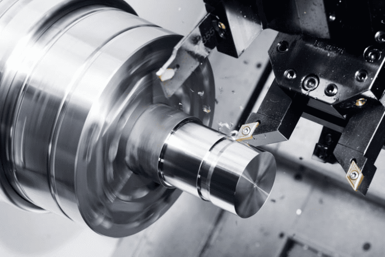
Produce straight, controlled bores in shafts, manifolds, tooling and precision components with the drilling route selected from diameter, depth, material and acceptance requirements. Mockup connects DFM, process selection, workholding and inspection before material is released.
Each route is reviewed from the drawing, functional datums, material behavior, quantity and required evidence.
ENGINEER REVIEWEDControlled pecking and evacuation for moderate depth-to-diameter ratios.
ENGINEER REVIEWEDGuided high-pressure coolant route for long, straight bores.
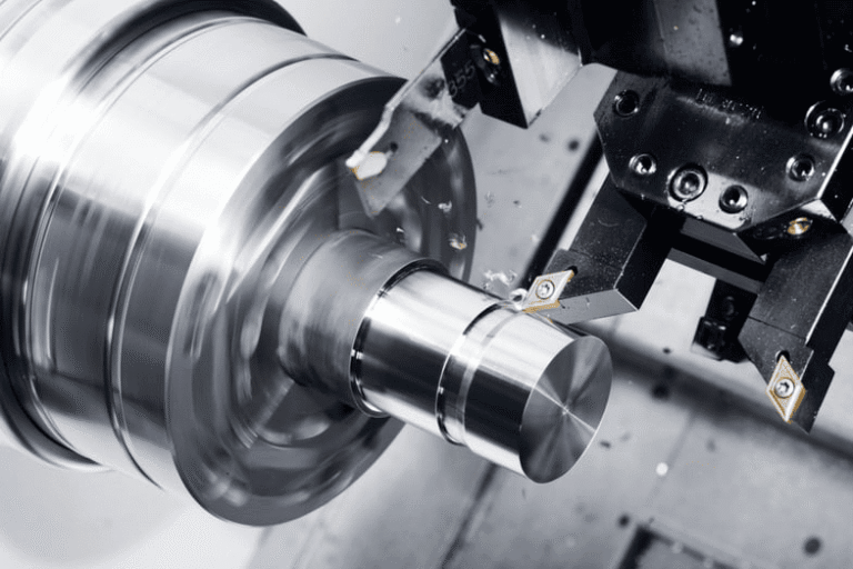 ENGINEER REVIEWED
Tool, runout and contamination control for sensitive small bores.
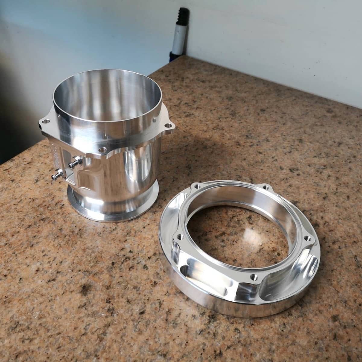 ENGINEER REVIEWED
Entry, bottom, breakthrough and burr condition planned from the drawing.
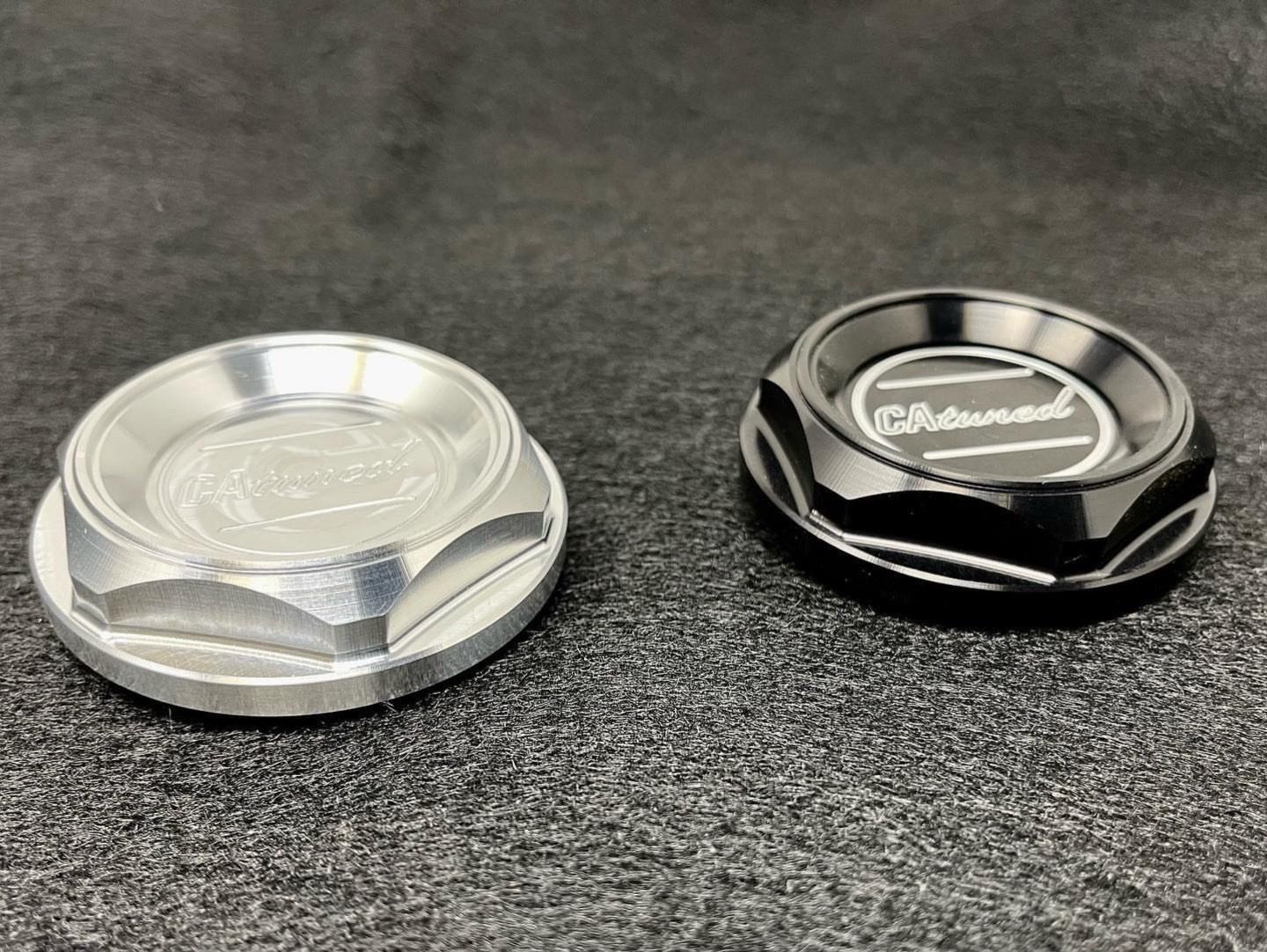 ENGINEER REVIEWED
Cross-hole timing and breakthrough controlled for manifolds and fluid parts.
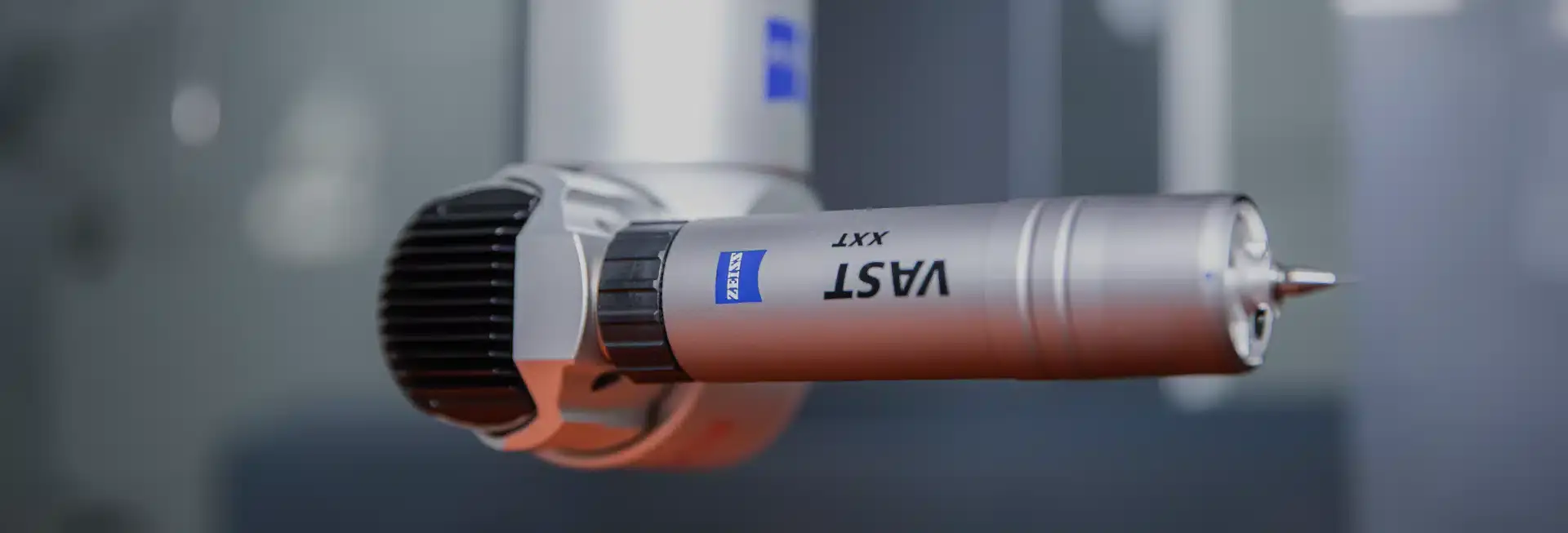 ENGINEER REVIEWED
Reaming, boring or honing coordinated when drilling alone is not the final process.
Compare manufacturing routes against geometry, material, quantity and the feature that controls acceptance.
Moderate tool reach
High depth ratio
Peck evacuation
Pressure coolant
General bore quality
Improved guidance
Flexible setup
Dedicated support
Accessible holes
Long straight bores
Lower route complexity
Special process review
Keep engineering assumptions, revision and acceptance criteria connected throughout the order.
Confirm geometry, material, quantity, CTQ features and open questions.
Choose operations, tools, datums, fixture strategy and inspection points.
Run the approved sequence with in-process checks where risk requires them.
Inspect the delivered condition and supply agreed records.
These values define the review inputs. The approved quotation and drawing control final capability.
A result is useful only when the functional requirement and the evidence used to accept it are aligned.
A result is useful only when the functional requirement and the evidence used to accept it are aligned.
Resolve access, datum and inspection questions before manufacturing release.
A flat, supported entry improves guidance and reduces walk.
Separate drill-point depth from required full-diameter depth.
Avoid blind geometry that traps chips without an evacuation strategy.
Identify whether flow, alignment, sealing or fastener access controls the bore.
Manufacturing routes are adapted to the functional geometry and program stage.
Long and intersecting passages with position and burr control.
Axial bores related to journals, centers and rotating datums.
Cooling, lubrication and sensor passages in precision structures.
Upload the current 3D model and controlled drawing with material, quantity, finish, critical characteristics and inspection requirements.
Upload CAD files↗A hole is commonly treated as deep when depth is several times diameter, but the practical threshold depends on tool, material and acceptance needs.
Yes, when geometry and bore requirements justify the route; final capability is confirmed during review.
Potentially. Diameter, depth, material, entry condition, straightness and inspection method must be reviewed together.
Methods can include gauges, depth checks, CMM position, borescope review and flow or functional testing.
Send the complete CAD package and identify the features that control fit, motion, sealing, appearance or performance.