
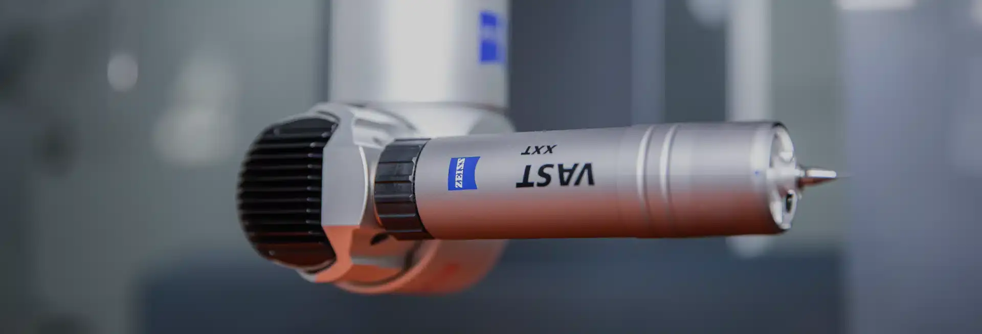
A practical guide to assigning CNC tolerances from function, choosing meaningful datums and fits, accounting for material and finishing, and building an inspection plan that can verify the result.
A tolerance is a functional decision—not a machine setting.
Every manufactured feature varies. Tolerancing defines how much variation the assembly can accept while continuing to fit, seal, align, move or carry load. The smallest possible number is rarely the best specification; the useful number is one that protects function and can be produced and verified repeatedly.
Begin with the interfaces that determine performance: bearing seats, sliding fits, sealing faces, locating pins, optical axes, connector positions and mating planes. Non-critical stock-removal dimensions can usually follow a general tolerance, while these functional relationships receive individual size or geometric controls.
Machine positioning resolution does not equal finished-part accuracy. Tool deflection, workholding, stock stress, thermal change, wall stiffness, cutter wear and datum transfers all enter the result. A tolerance should therefore be reviewed as part of a process chain rather than copied from a machine brochure.
Choose the tolerance language that matches the failure mode.
A plus/minus size tolerance controls length, diameter or thickness, but it does not always control how features relate. A bore can be within diameter limits and still be misplaced; a mounting face can meet thickness while remaining bowed. Form, orientation and location controls exist to describe those different conditions.
Use size limits for features whose upper and lower material boundaries drive function. Use flatness, straightness, circularity or cylindricity when the shape itself matters. Use perpendicularity, parallelism, position or profile when a feature must relate to one or more datums.
Avoid controlling the same requirement twice. Tight coordinate dimensions combined with position tolerance can create conflicting acceptance zones. A clearer drawing establishes basic dimensions for theoretically exact location and lets the feature-control frame define the permitted geometric variation.
| Functional requirement | Typical control | Datum needed? | Common inspection |
|---|---|---|---|
| Shaft or bore fit | Size limits / ISO fit | No for size alone | Micrometer or bore gauge |
| Sealing plane | Flatness; surface texture | No for flatness | CMM, indicator or optical flat |
| Hole pattern location | Position | Yes | CMM or functional gauge |
| Face alignment | Parallelism / perpendicularity | Yes | CMM or indicator setup |
| Complex cast or machined contour | Profile of a surface | Usually | CMM or 3D scan |
| Rotating feature | Circular / total runout | Yes | Indicator between functional datums |
Use a general tolerance for ordinary dimensions, then override only where function requires it.
General tolerances prevent a drawing from becoming crowded with repeated plus/minus values. ISO 2768-1 defines classes for linear and angular dimensions without individual tolerance indications. It applies only when the drawing invokes the standard and a specific dimension does not carry its own requirement.
Class m is a common medium starting point for machined parts, but it is not automatically Mockup's default and it is not suitable for every geometry or material. The title block, purchase specification and released revision must state the applicable system.
General tolerances do not replace engineering judgment. A 200 mm thin plastic plate and a 200 mm rigid steel block can share the same nominal size while responding very differently to clamping, temperature and stress. Critical features still need explicit review.
| Nominal dimension range | Permissible deviation |
|---|---|
| 0.5–3 mm | ±0.10 mm |
| >3–6 mm | ±0.10 mm |
| >6–30 mm | ±0.20 mm |
| >30–120 mm | ±0.30 mm |
| >120–400 mm | ±0.50 mm |
| >400–1000 mm | ±0.80 mm |
| >1000–2000 mm | ±1.20 mm |
Treat tolerance bands as review triggers, not universal capability promises.
The same tolerance can be routine on one feature and high-risk on another. A ±0.02 mm bore in a rigid aluminum block is different from ±0.02 mm across two setups, after heat treatment or on a flexible polymer wall. Feature size, aspect ratio, access and datum continuity determine the real difficulty.
The table below is a useful RFQ triage framework for CNC milling and turning. It describes the level of process planning normally required, not guaranteed acceptance across every part. Mockup confirms feature-specific capability only after reviewing the model, drawing, material, finish, quantity and inspection method.

| Tolerance band | Typical interpretation | Likely process response | Inspection planning |
|---|---|---|---|
| ±0.10 mm and wider | General machining range | Standard setup and finishing | Caliper, micrometer or standard gauge |
| ±0.05 mm | Controlled feature | Stable datum and planned finish pass | Micrometer, bore gauge or height method |
| ±0.02 mm | Precision feature | Rigid setup, tool-wear and thermal attention | CMM or dedicated precision gauge |
| ±0.01 mm | High-precision review | Process-specific finishing may be needed | Measurement uncertainty must be demonstrated |
| Below ±0.01 mm | Special process territory | Grinding, honing, lapping or matched process review | Dedicated metrology and environmental control |
Tolerance stability depends on what the part does after the cutter leaves.
Material removal redistributes residual stress. Thin walls relax, long parts bend, polymers respond to heat and moisture, and hardened materials can move during thermal processing. A dimension that is reachable at the machine may not remain stable through unclamping, finishing, transport and service.
Aluminum machines efficiently but thin plates can move when large volumes are removed from one side. Austenitic stainless steel retains cutting heat and can work-harden. Titanium concentrates heat near the cutting edge. Nylon and PTFE can deform under modest clamping or measurement force. Each behavior changes how a tight feature should be fixtured and inspected.
Balanced stock removal, intermediate stress relief, rough-and-finish sequencing or leaving final stock for a later operation can improve stability. The right route depends on part geometry and material condition rather than a generic tolerance chart.
| Material | Primary dimensional risk | Design / process response | Inspection condition |
|---|---|---|---|
| Aluminum | Thin-wall or plate movement | Balanced removal; stable datum pads | After unclamping and finishing |
| Stainless steel | Heat and work hardening | Positive cutting; controlled finish pass | Temperature stabilized |
| Tool steel | Heat-treatment distortion | Rough, treat, then grind / finish | Final hardness condition |
| Titanium | Heat and elastic recovery | Rigid short tools; controlled engagement | After full relaxation |
| POM / acetal | Thermal movement and creep | Gentle clamping; realistic fits | Defined room temperature |
| Nylon | Moisture and flexibility | Condition material; avoid metal-like controls | Defined moisture condition |
| PTFE | Creep and measurement deformation | Functional tolerances; low measurement force | Defined restraint and temperature |
State whether the dimension applies before or after finishing.
Anodizing, plating, powder coating and painting change the surface after machining. Some processes add measurable thickness; others alter the substrate or edge condition. If a fit, thread, grounding point or sealing face is critical, the process route must define allowance, masking and the inspection stage.
A coating thickness specified per surface affects a diameter twice—once on each side. Internal and external features may also build differently depending on process access and current distribution. Cosmetic requirements can add blasting or polishing before coating, which changes the starting surface.
The drawing should identify masked features and specify whether acceptance applies in the finished condition. When color or texture matters, define cosmetic zones and viewing criteria separately from dimensional requirements.
| Finish family | Dimensional concern | Features commonly reviewed | Control approach |
|---|---|---|---|
| Type II anodize | Oxide growth and edge response | Fits, threads, contacts | Allowance or masking |
| Hard anodize | Greater functional buildup | Bearing seats, sliding fits | Pre-machine allowance; verify after finish |
| Electroless nickel | Relatively uniform deposit | Bores, shafts, sealing lands | Specify thickness and final size |
| Powder coat / paint | Higher, variable film build | Threads, holes, mating faces | Mask functional areas |
| Bead blast / polish | Material texture change | Cosmetic and sealing faces | Sample and roughness requirement |
| Passivation | Minimal intended buildup | Stainless cleanliness | Process specification; inspect final condition |
A tolerance is incomplete until the measurement method can make the decision.
Inspection equipment answers different questions. Calipers are efficient for broad external dimensions; micrometers resolve controlled sizes; bore gauges compare internal diameters; CMMs evaluate datums and geometric relationships. Selecting the tool after production can expose features that are difficult or impossible to verify consistently.
A preferred measurement system should have substantially better resolution and uncertainty than the tolerance being judged. A 4:1 test-accuracy ratio is a practical planning target, while critical programs may demand a formal uncertainty budget or measurement-system analysis. The applicable customer or quality requirement controls.
Temperature, cleanliness, contact force, datum simulation and sampling also affect the result. First-article inspection is the right time to resolve interpretation, but it does not replace ongoing process controls for dimensions vulnerable to tool wear or drift.
| Feature | Typical method | Best suited to | Key limitation |
|---|---|---|---|
| Broad external size | Caliper | Fast general inspection | Limited for tight tolerances |
| Shaft / thickness | Micrometer | Controlled two-point size | Does not evaluate form alone |
| Precision bore | Bore gauge / air gauge | Repeat internal size | Requires master and access |
| Height / location | Height gauge | Planar datum relationships | Setup and probe access |
| Position / profile | CMM | 3D datum-based geometry | Program, uncertainty and access |
| Surface texture | Profilometer | Ra / profile parameters | Trace location must be defined |
| Runout | Indicator fixture | Rotational functional behavior | Datum simulation controls result |
Locate a dowel-hole pattern from the interfaces that assemble the part.
Consider a machined fixture plate that sits on a base, registers against a side rail and uses two dowel holes to locate a removable module. The functional question is whether the module will assemble repeatably—not whether each hole center matches an arbitrary edge coordinate.
The mounting plane can establish datum A, the side locating face datum B and an end face datum C. Basic dimensions define the theoretically exact dowel locations. A position tolerance relative to A, B and C controls the cylindrical tolerance zones for both hole axes. Hole size limits separately control the dowel fit.
Inspection can simulate A, align to B, clock from C and evaluate both axes in one coordinate system. This matches the assembly and avoids a chain of plus/minus dimensions. If maximum material condition is appropriate, bonus tolerance and a functional gauge may protect assembly while allowing more manufacturing variation—but that choice requires stack-up analysis.
| Design intent | Drawing requirement | Datum reference | Verification |
|---|---|---|---|
| Plate seats flat | Flatness of mounting plane | Datum feature A | Surface plate / CMM |
| Side rail establishes location | Perpendicularity or profile | A | B | CMM or indicator |
| Dowel fits hole | Hole size limits | Size feature | Pin / bore gauge |
| Dowel pattern locates module | Position of hole pattern | A | B | C | CMM or functional gauge |
| Fasteners clear assembly | Clearance-hole size / position | A | B | C as needed | Gauge or CMM |
Release one coherent tolerance system.
Before quotation, confirm that the model, drawing and notes do not contradict one another. The drawing should identify the governing standard, units, general tolerance, datums, individually controlled features, finish condition and inspection deliverables.
Separate functional requirements from preferred manufacturing methods unless the method itself is controlled. Avoid using decimal places as an accidental tolerance system. Check that basic dimensions are theoretically exact, reference dimensions are clearly marked and every feature-control frame points to valid datum features.
For the fastest review, send a STEP or Parasolid model with the controlled PDF drawing, material grade, quantity, finish and documentation requirements. Mockup will flag features where geometry, material, process or measurement makes the stated tolerance high-risk before production release.
Guidance connected to real manufacturing decisions.
Mockup helps product teams move from CAD review and DFM through manufacturing, inspection and repeat production. Our engineering guides translate that operating experience into practical decisions you can apply before requesting a quote.
Questions from engineering teams.
What is a standard CNC machining tolerance?+
There is no single value suitable for every part. ISO 2768 or another stated general tolerance can cover ordinary dimensions, while functional fits and geometric relationships need feature-specific controls.
Can Mockup hold ±0.01 mm?+
Selected features may be reviewed at this level, but it is not a blanket capability across every size, material, geometry or setup. The process route and inspection method must be confirmed from the drawing.
Why do tighter tolerances increase cost?+
They can require more stable stock, dedicated workholding, slower finishing, thermal control, secondary processes and more capable inspection. Cost depends on the specific feature and its relationship to other features.
Should dimensions be inspected before or after finishing?+
The drawing should say. Functional dimensions affected by coating usually need allowance or masking and final verification in the finished condition.
When should I use GD&T instead of plus/minus tolerances?+
Use GD&T when form, orientation or location relative to functional datums matters more than an isolated coordinate or size.
What files are needed for tolerance review?+
Send a neutral 3D model and controlled PDF drawing with datums, tolerances, GD&T, material, finish, quantities and required inspection documentation.