
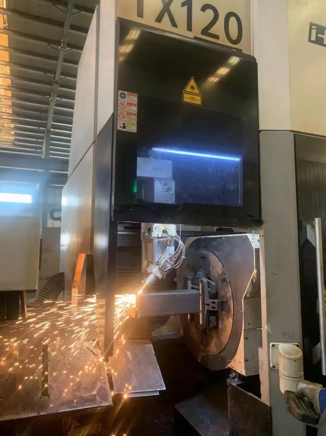
 DIGITAL PROFILES
01
Profile & Contour Cutting
Produce external profiles from simple plates and brackets to complex nested geometries with repeatable digital cut paths.
Cut precise profiles, holes and complex patterns without dedicated hard tooling. Mockup supports prototypes and production with bending, welding, finishing and inspection in one workflow.
Upload your DXF, DWG, 3D model or drawing with material, thickness, quantity and finish. We will review cutting geometry, tolerances and downstream fabrication.
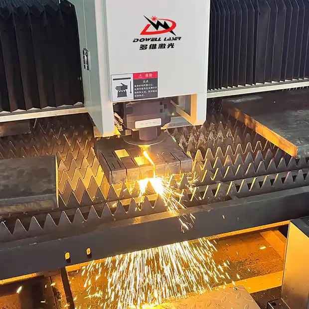
Turn digital geometry directly into flat metal parts for prototypes, revisions and production without dedicated profile tooling.
DIGITAL PROFILESProduce external profiles from simple plates and brackets to complex nested geometries with repeatable digital cut paths.
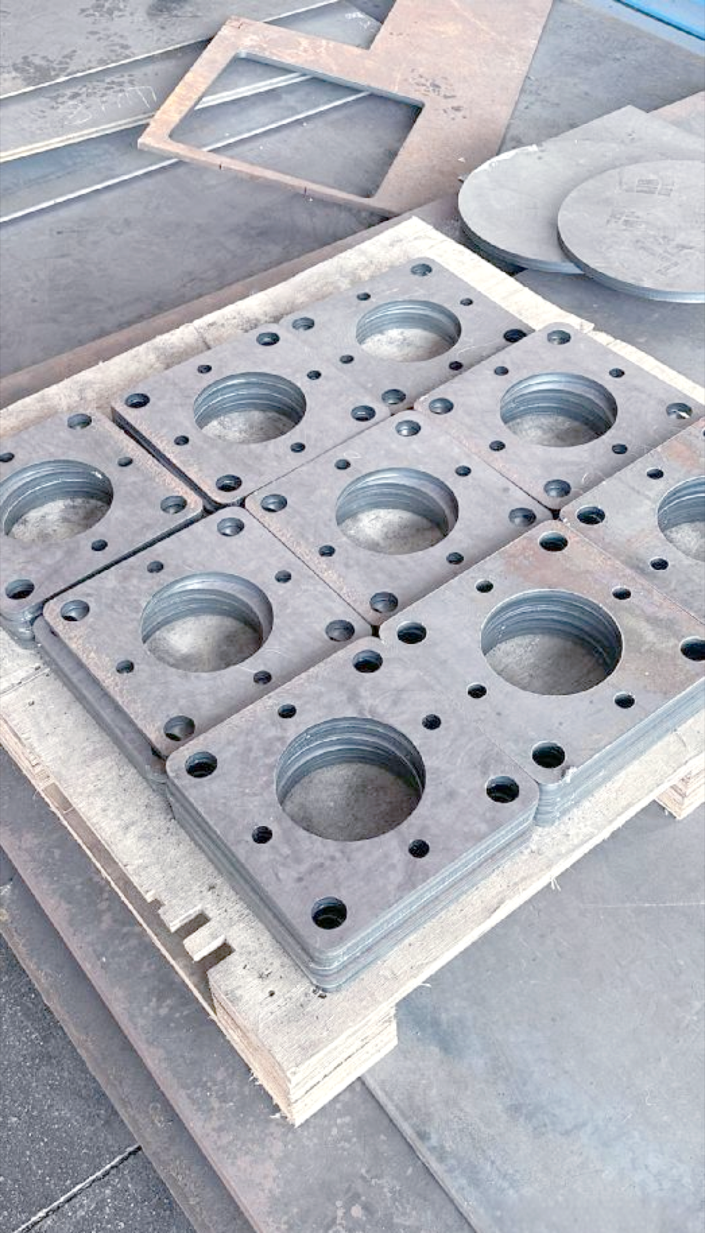 COMPLEX FEATURES
Cut mounting holes, slots, tabs, ventilation patterns and complex internal features directly from CAD geometry.
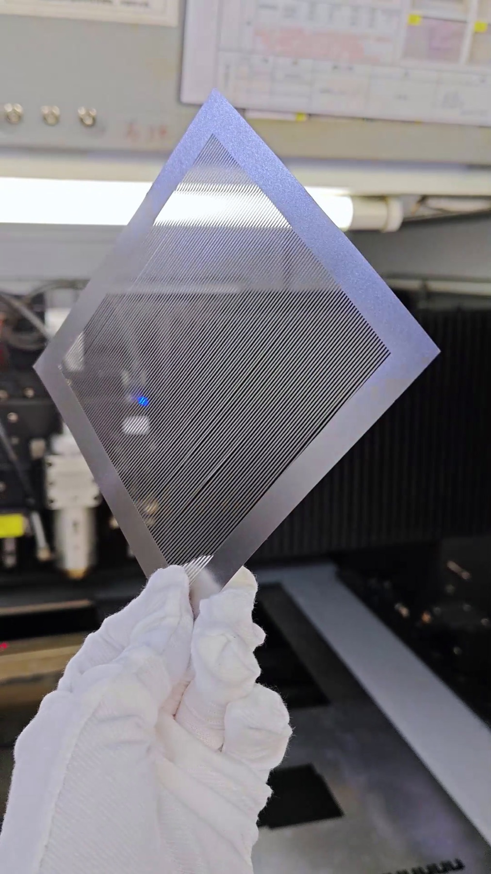 ACCURATE FLAT GEOMETRY
Produce shims, panels, covers and chassis blanks where accurate flat geometry is critical to downstream fit.
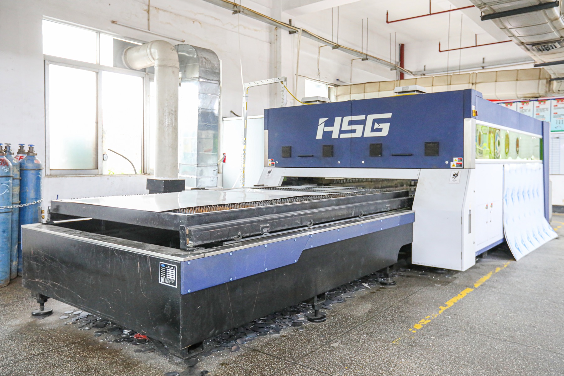 MATERIAL EFFICIENCY
Arrange multiple parts efficiently across each sheet to improve material utilization and reduce avoidable scrap.
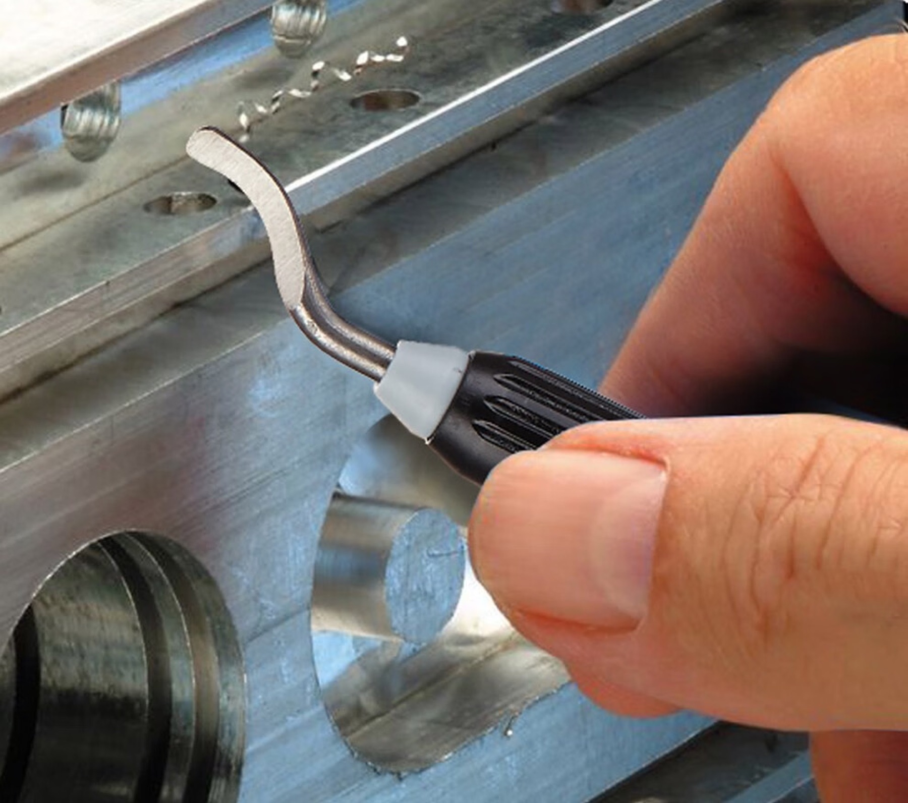 CONTROLLED EDGES
Supply parts as-cut or remove burrs, dross and sharp edges before forming, finishing or assembly.
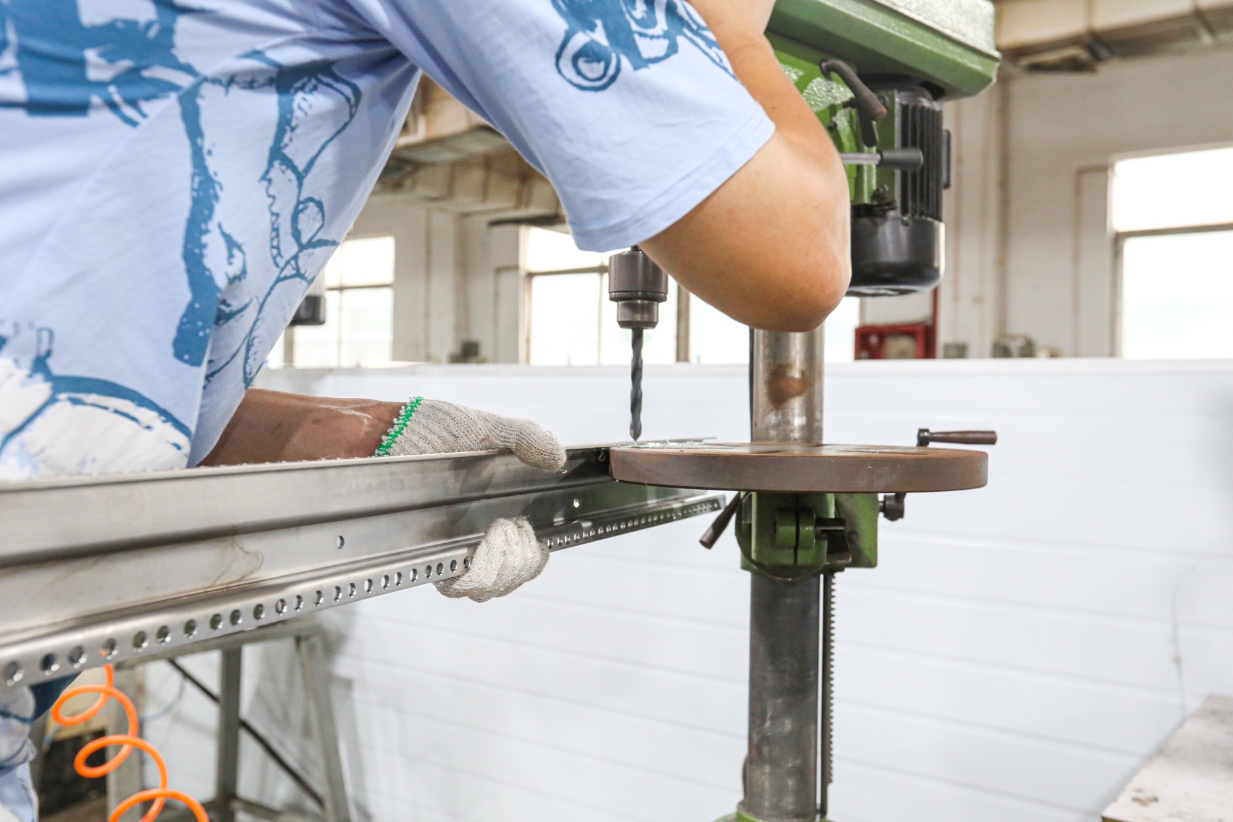 CUT TO FINISHED PART
Continue directly into bending, welding, hardware installation, finishing and assembly under one drawing revision.
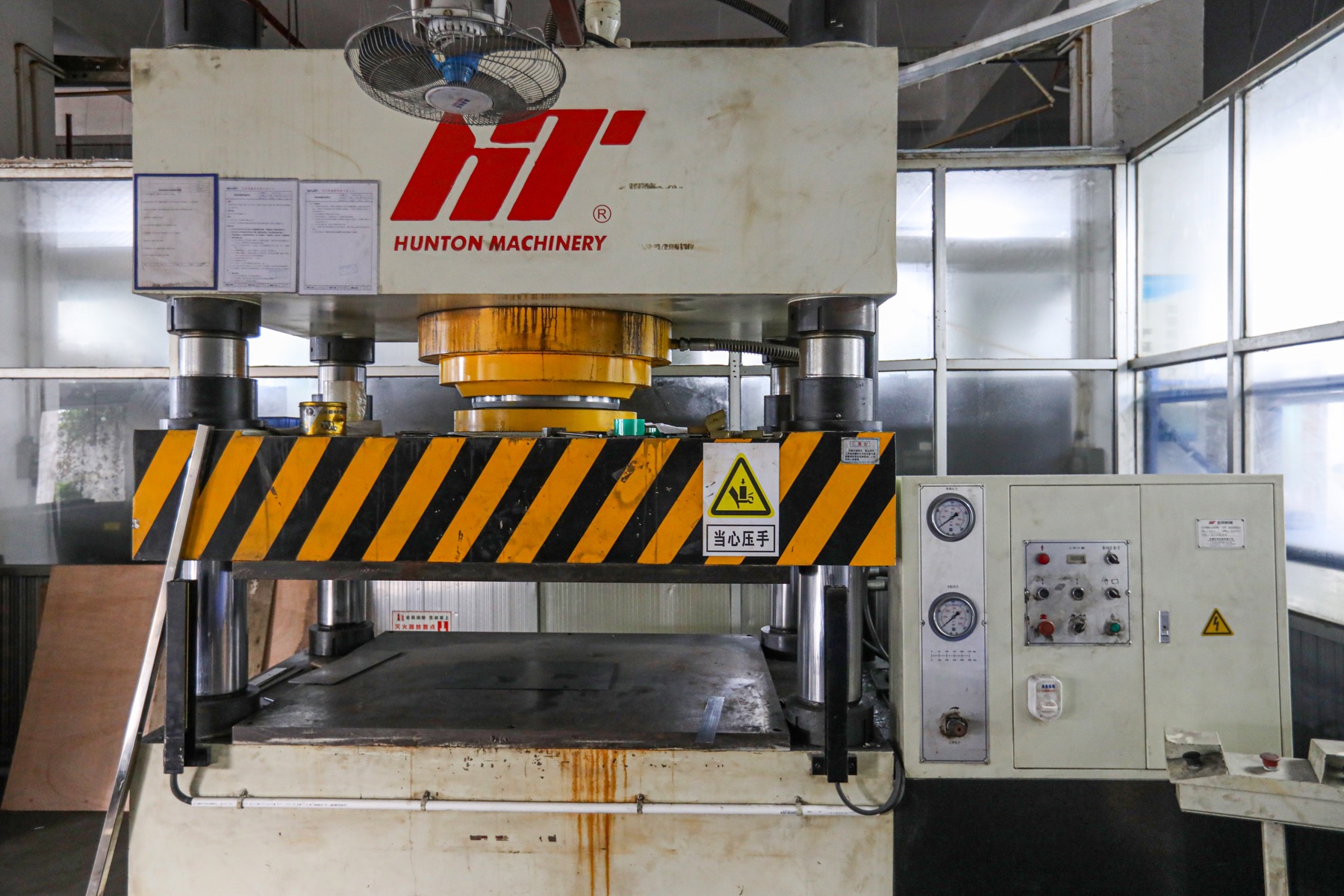
Laser cutting is strongest for complex 2D profiles, rapid prototypes and low-to-medium production volumes, with no dedicated profile tooling.
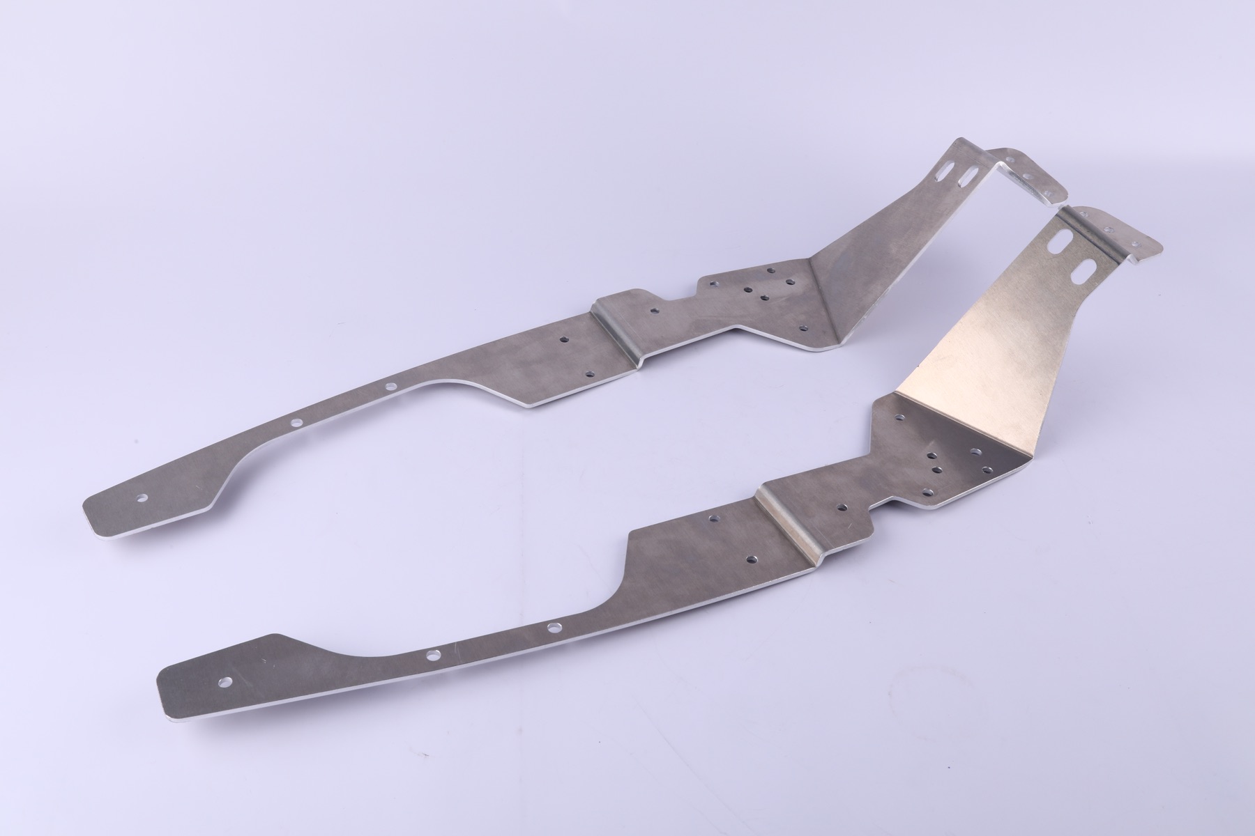
Digital cut path
Tool or alternate cutting route
High complexity
Feature- and route-dependent
Process-dependent edge
Selected for repeated features or low heat
Fast revisions
Volume-dependent
Prototypes and flexible batches
Standard features, heat-sensitive edges or sustained volume
No profile tooling
Tooling economics apply
Keep the approved CAD revision, material, downstream operations and inspection plan connected as volume grows.
Produce functional metal parts without dedicated tooling and move revised geometry quickly into the next iteration.
Support flexible batches with the same digital cutting process used during prototype validation.
Carry approved revisions, material specifications, secondary operations and inspection requirements into future releases.
Typical manufacturing ranges are reviewed against material grade, thickness, part size, small features, heat input and required edge quality.
Move from flat profiles to finished components with cutting, bending, welding, finishing and inspection coordinated around one drawing revision.
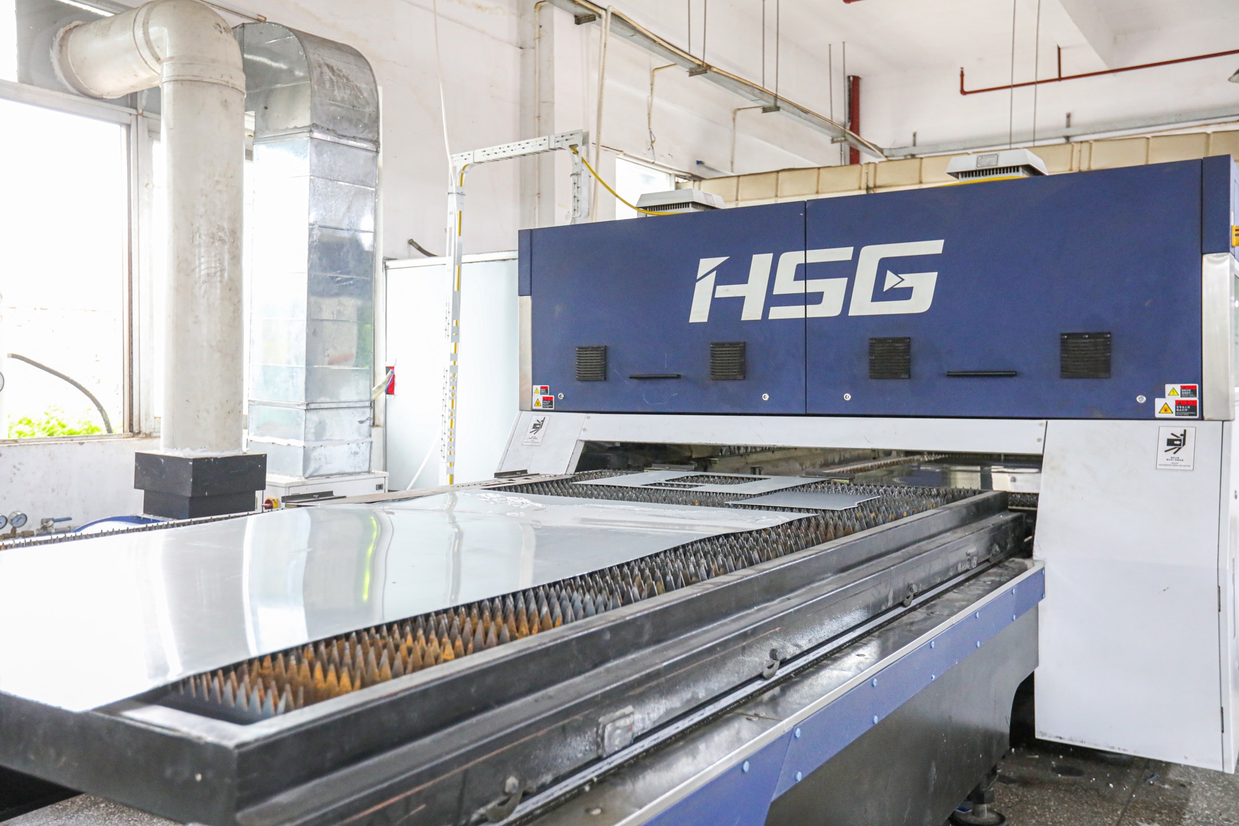
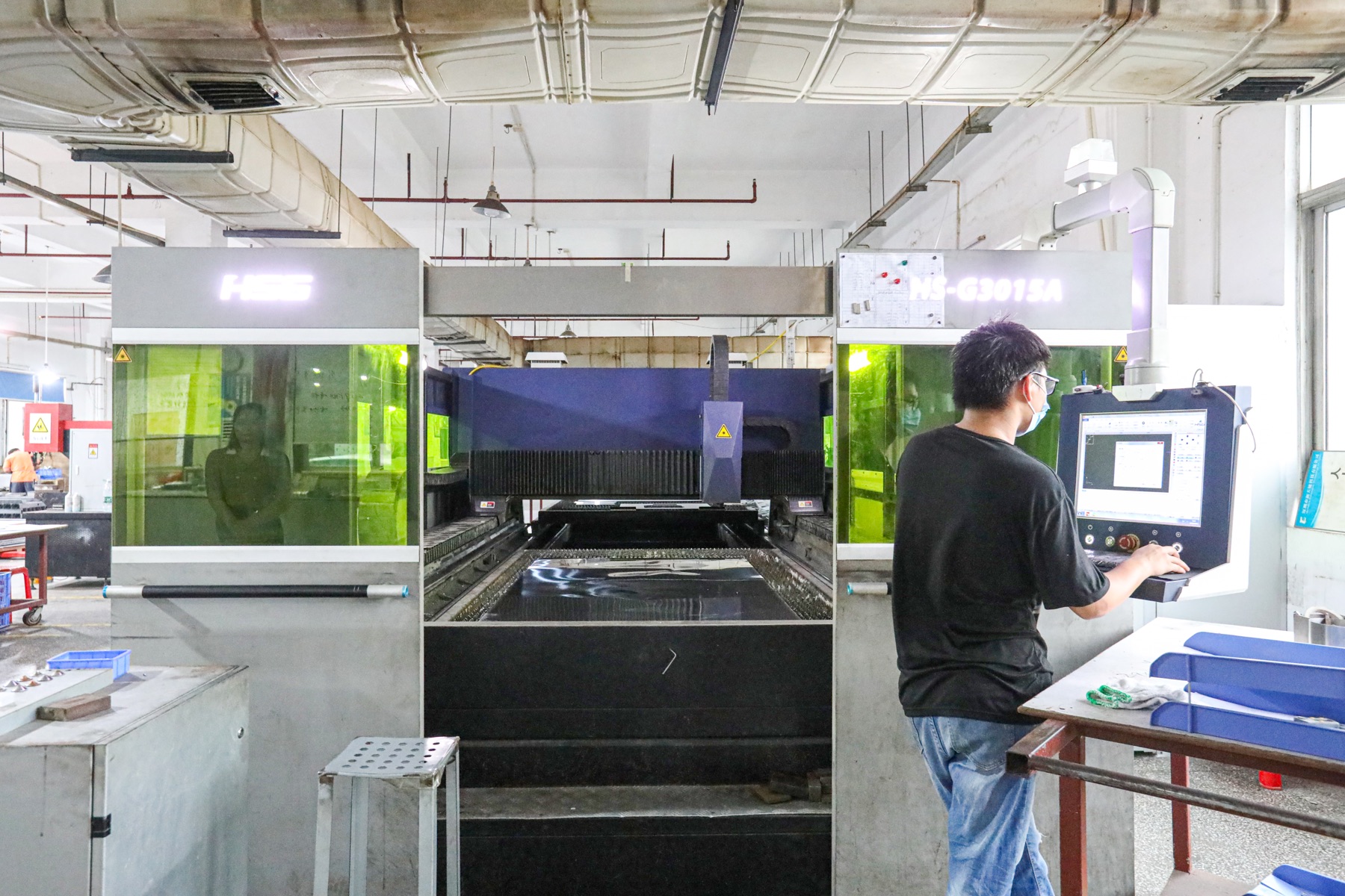
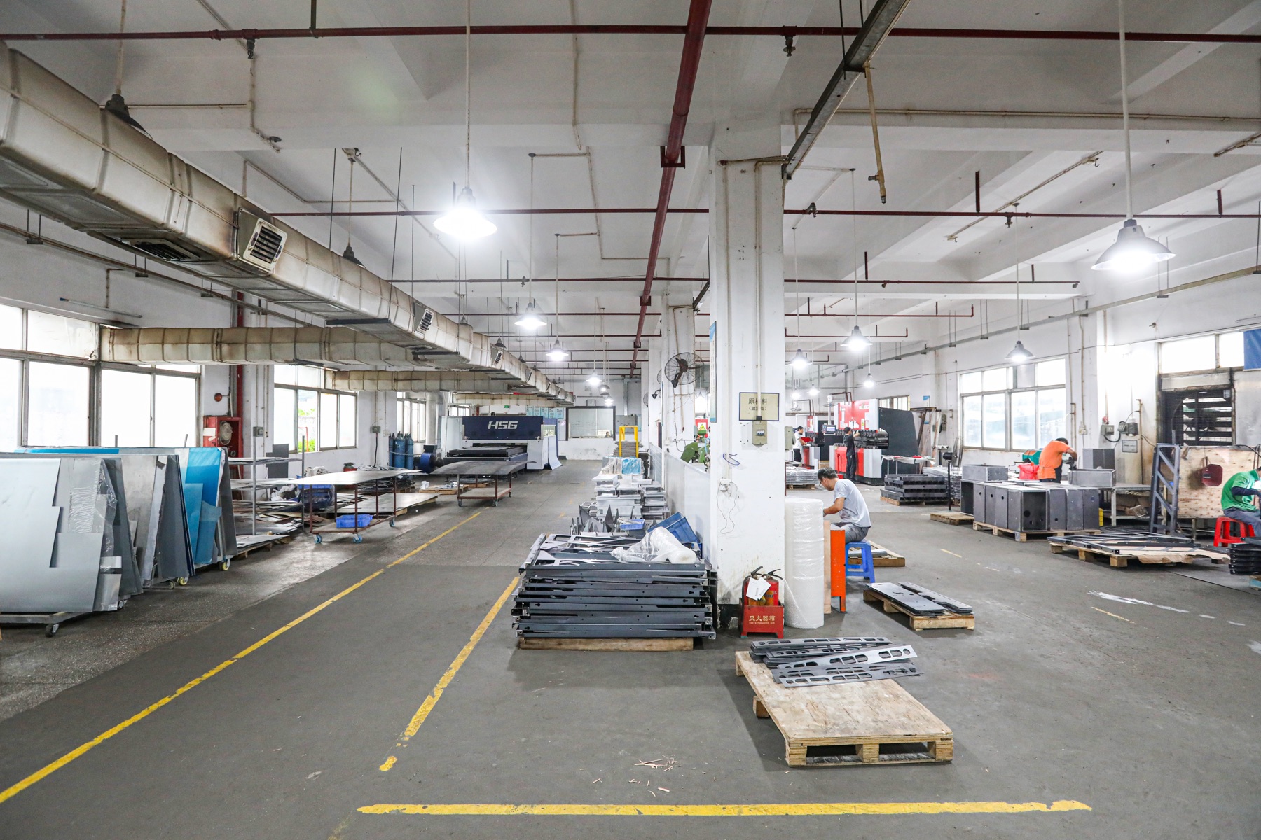
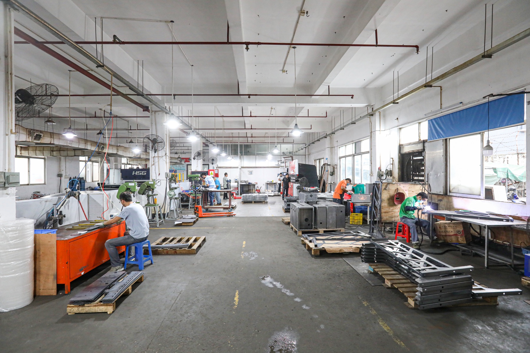
Compare common engineering metals by cutting behavior, edge quality, feature size and downstream fabrication needs.
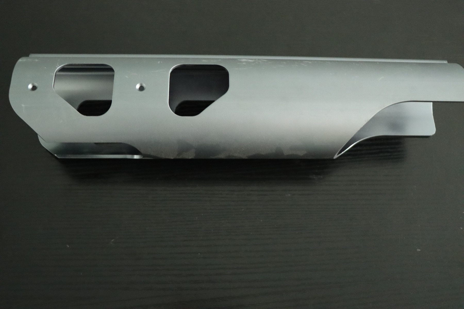
Cut quality must support bending, welding and assembly. Grain direction, protective film and cosmetic faces are controlled during nesting when specified.
Cut quality must support bending, welding and assembly. Grain direction, protective film and cosmetic faces are controlled during nesting when specified.
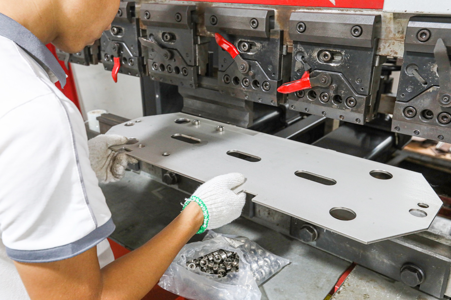
Good DFM improves edge quality, material utilization and downstream fabrication.
Size minimum holes and narrow webs around material thickness.
Avoid tiny internal features dominated by kerf width.
Keep bend and marking lines distinct from cut geometry.
State whether micro-joints or holding tabs are acceptable.
Identify grain direction, cosmetic faces and protective-film requirements.
For formed parts, control interfaces around final geometry rather than the flat blank alone.
Coordinate downstream operations around the final drawing so cut features, formed dimensions, cosmetic surfaces and assembly interfaces remain controlled.
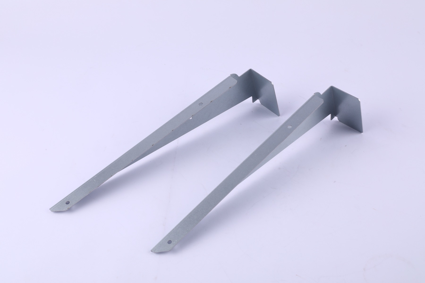
Press-brake forming planned around bend radius, allowance, springback and hole-to-bend relationships.
Explore sheet metal fabrication↗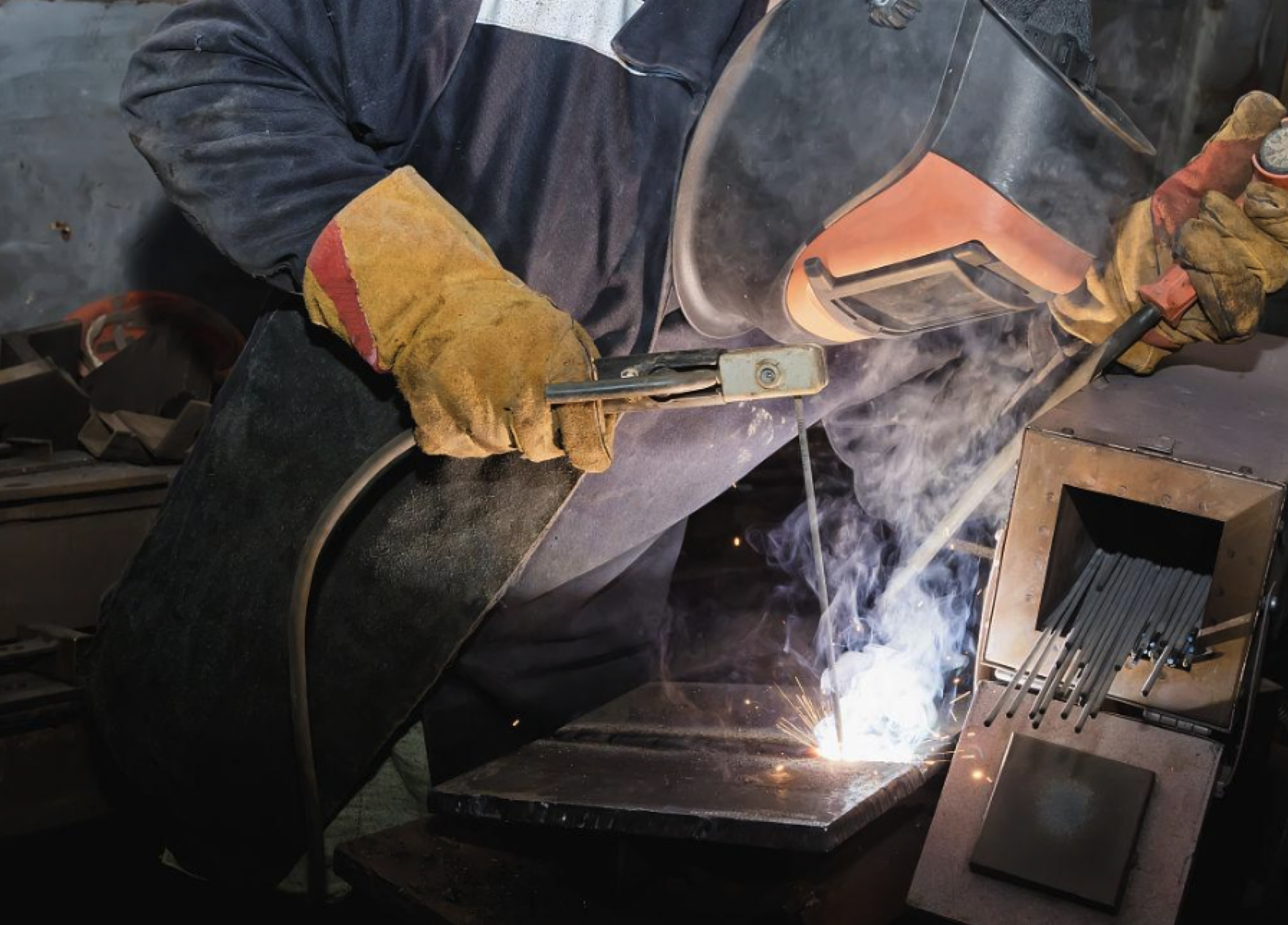
TIG, MIG, spot welding, riveting and fastening with attention to weld sequence and distortion.
Explore sheet metal fabrication↗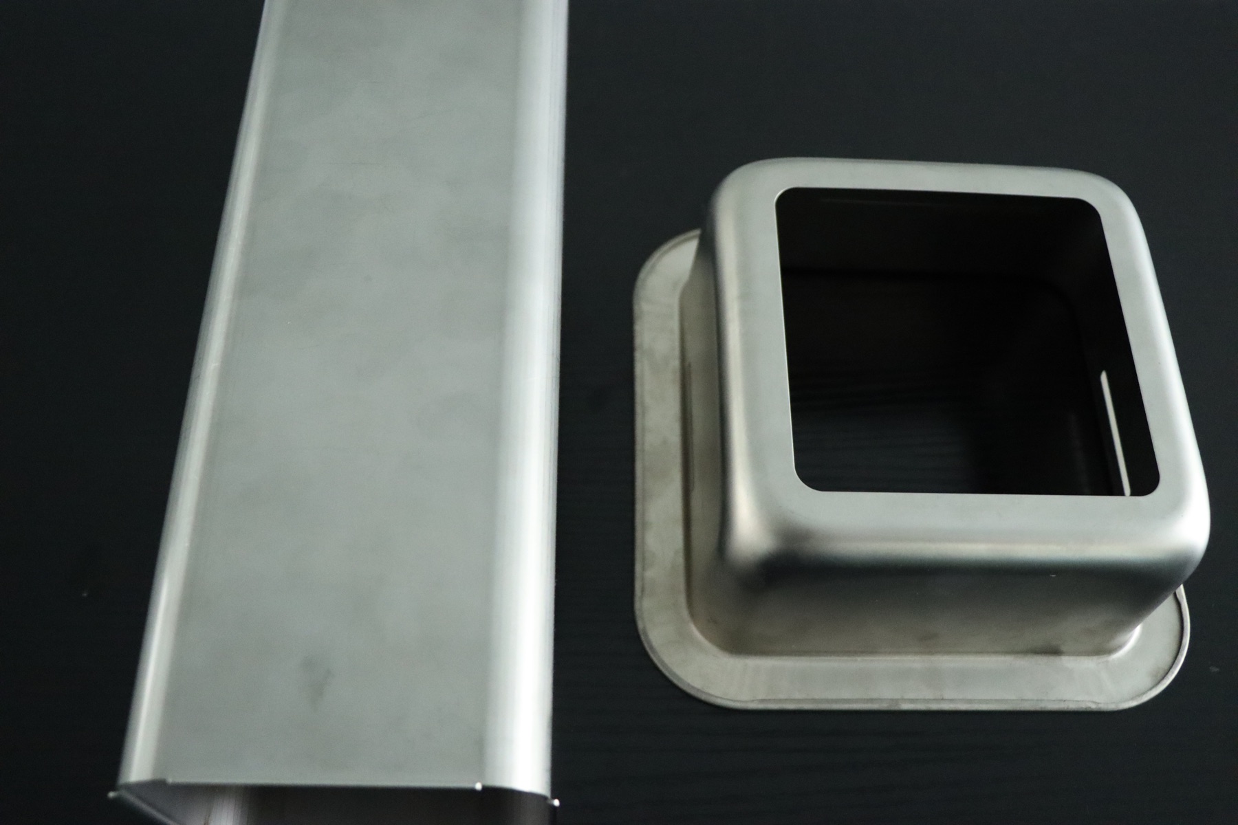
PEM nuts, studs, standoffs, rivet nuts and inserts installed to drawing orientation.
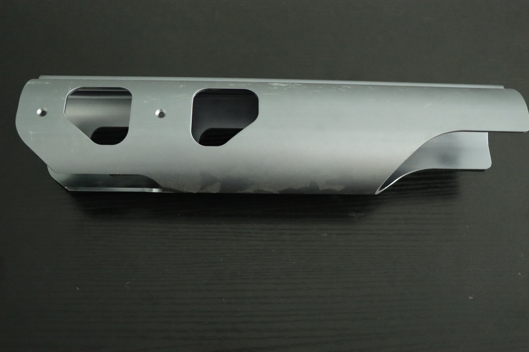
Edge rounding, brushing and polishing improve handling, assembly and appearance.
Explore surface finishing↗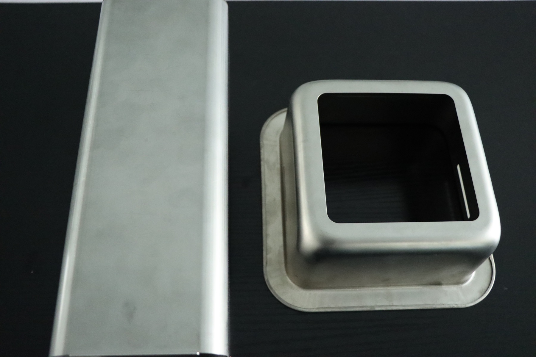
Powder coating, anodizing, passivation, plating, blasting, brushing, polishing and painting.
Explore surface finishing↗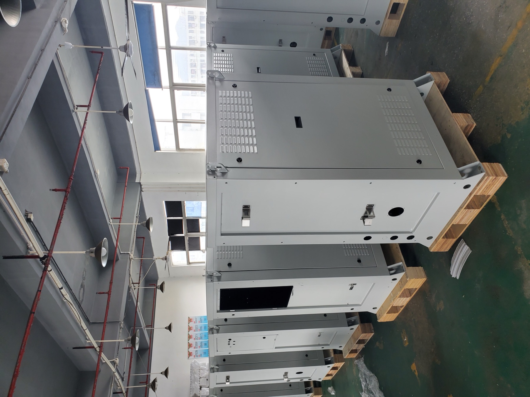
Combine formed parts with machined components, hardware and purchased parts before inspection.
Deliver flat blanks or complete fabricated components across common engineered product categories.
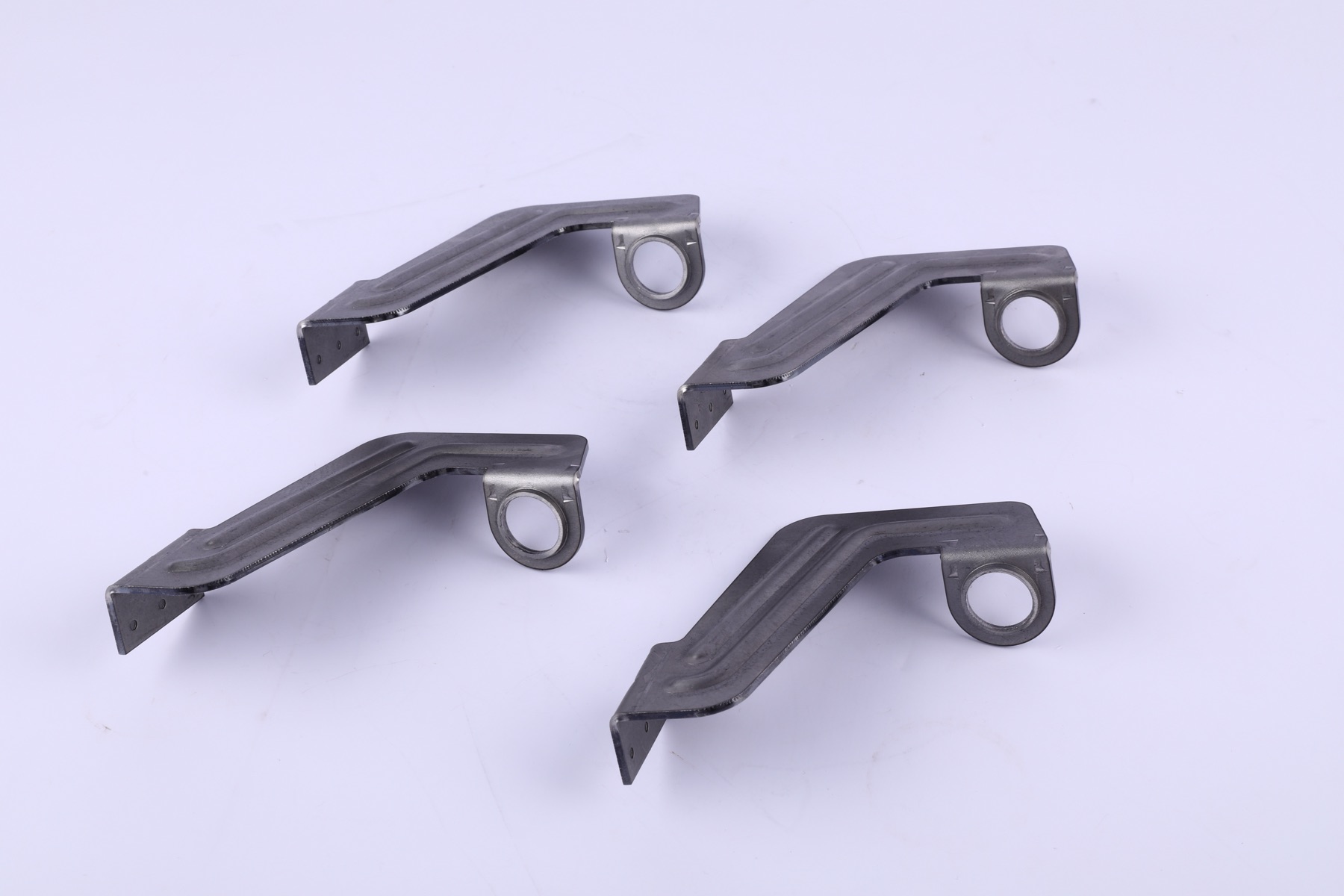
Flat or formed mounting components with holes, slots, tabs and assembly features.
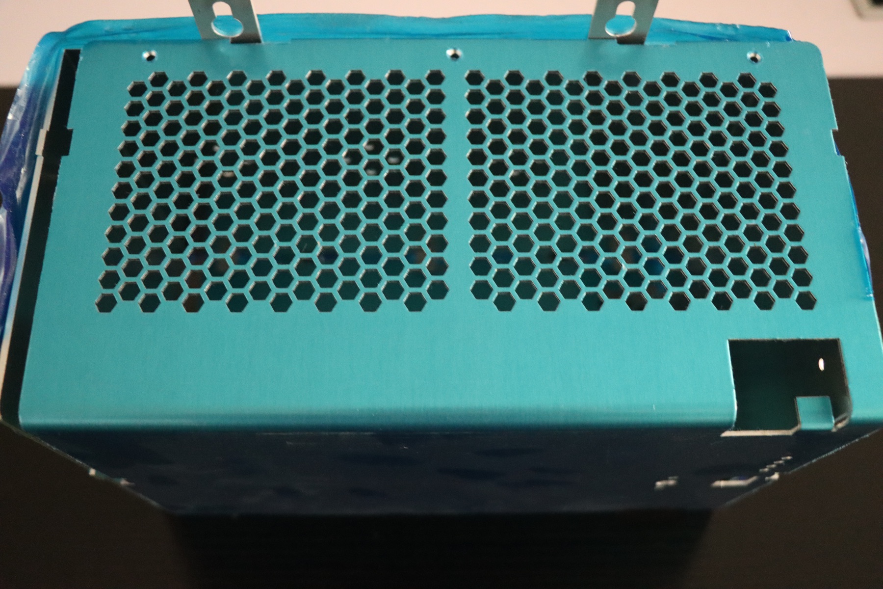
Equipment panels, access covers and guards with complex openings or ventilation patterns.
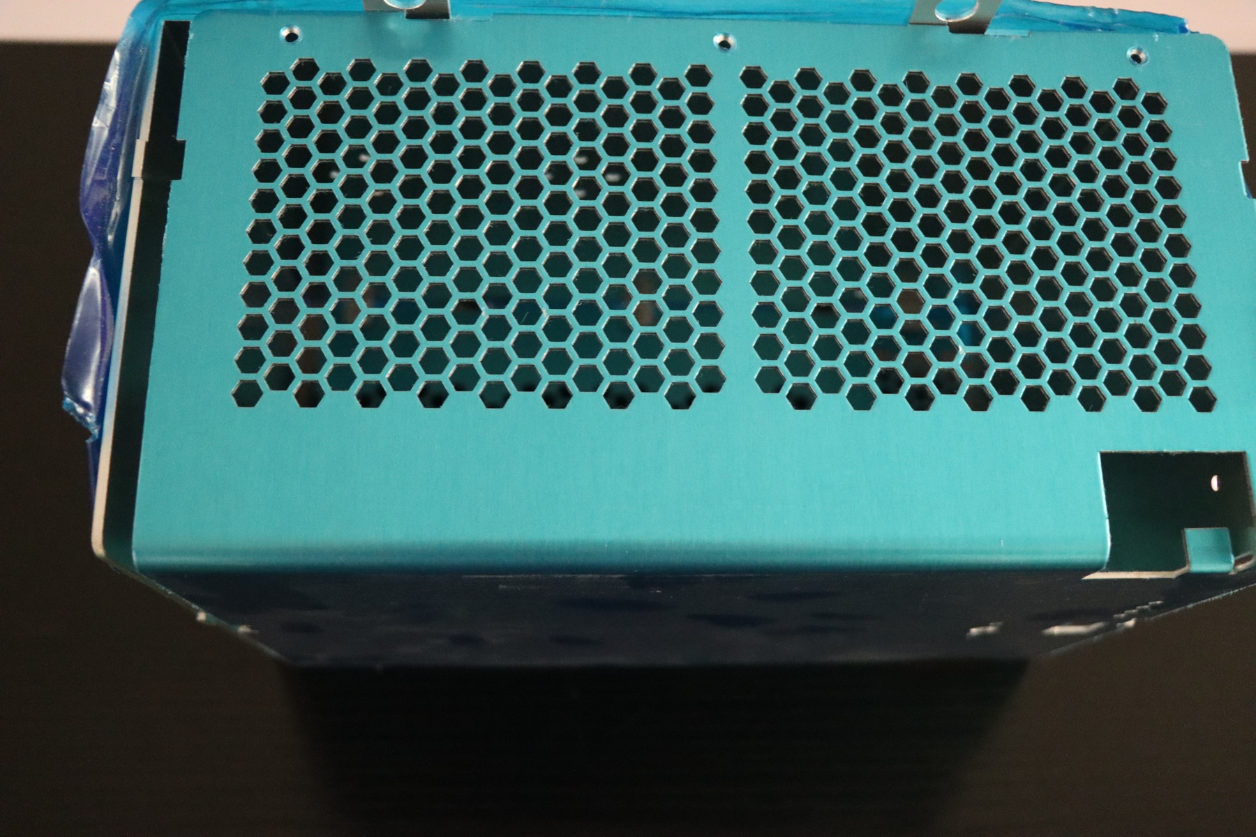
Cut blanks that continue through bending, hardware and finishing into complete housings.
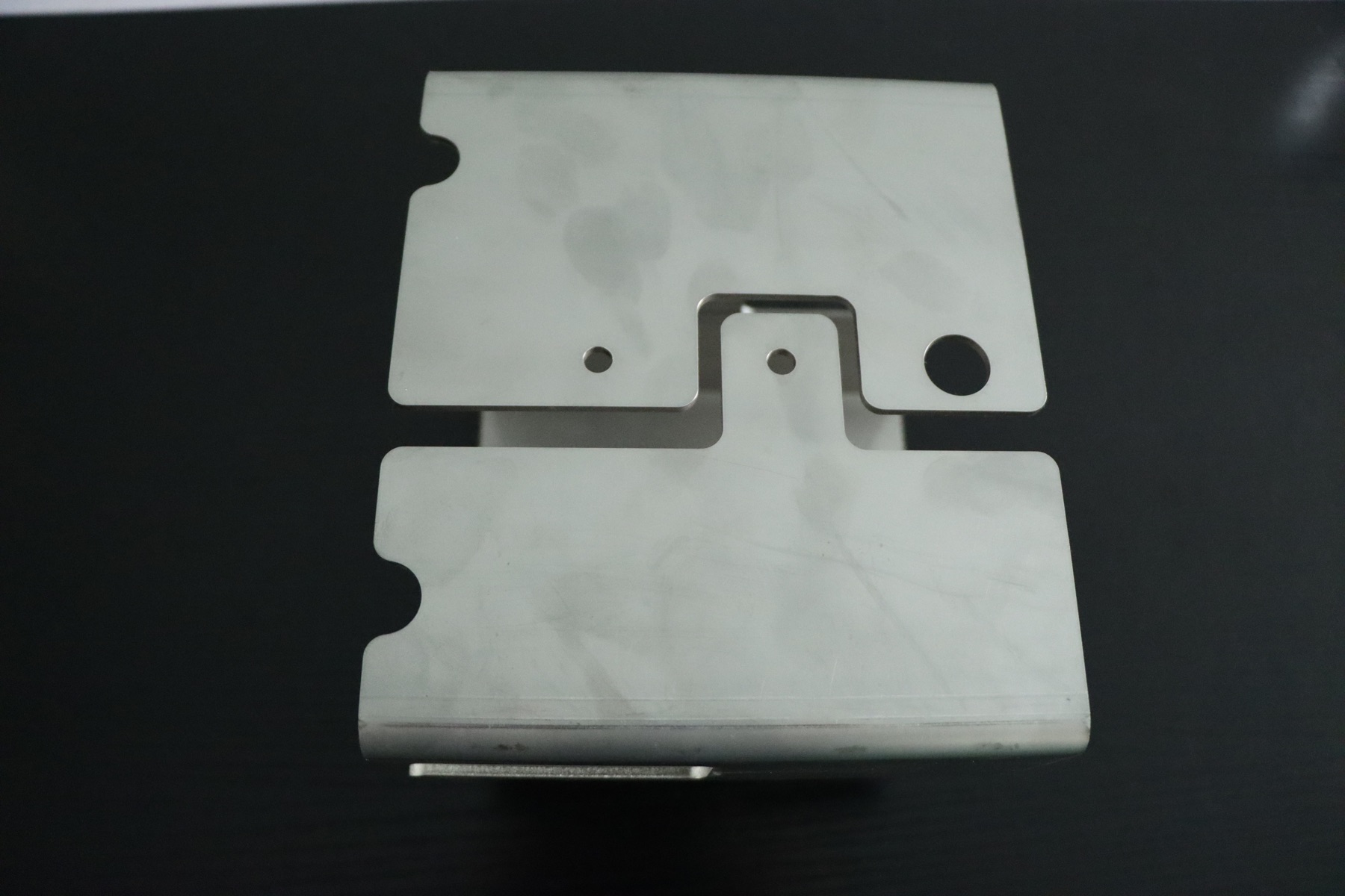
Thin components where profile geometry, hole location and thickness are critical.
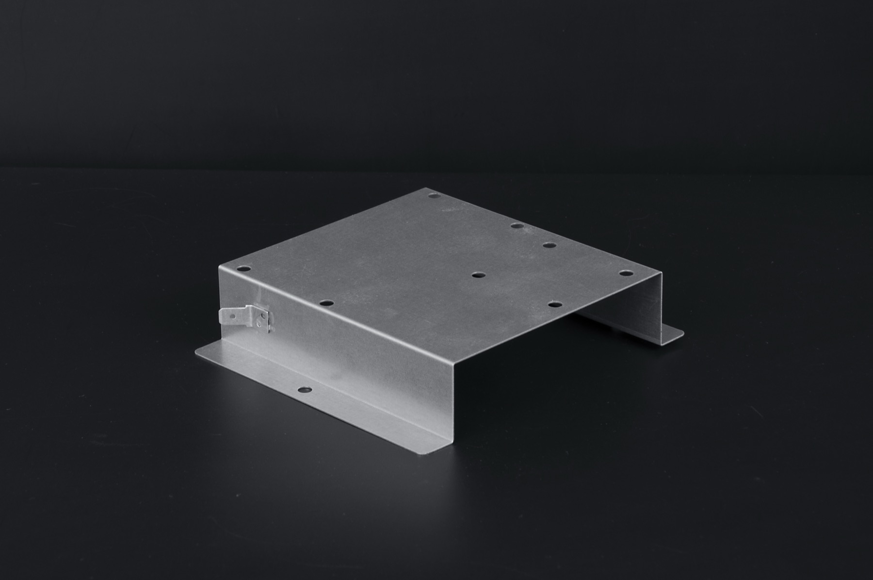
Machine guards, frames and structural parts ready for forming, welding and finishing.
Each route connects flat geometry to the final functional and inspection requirements.
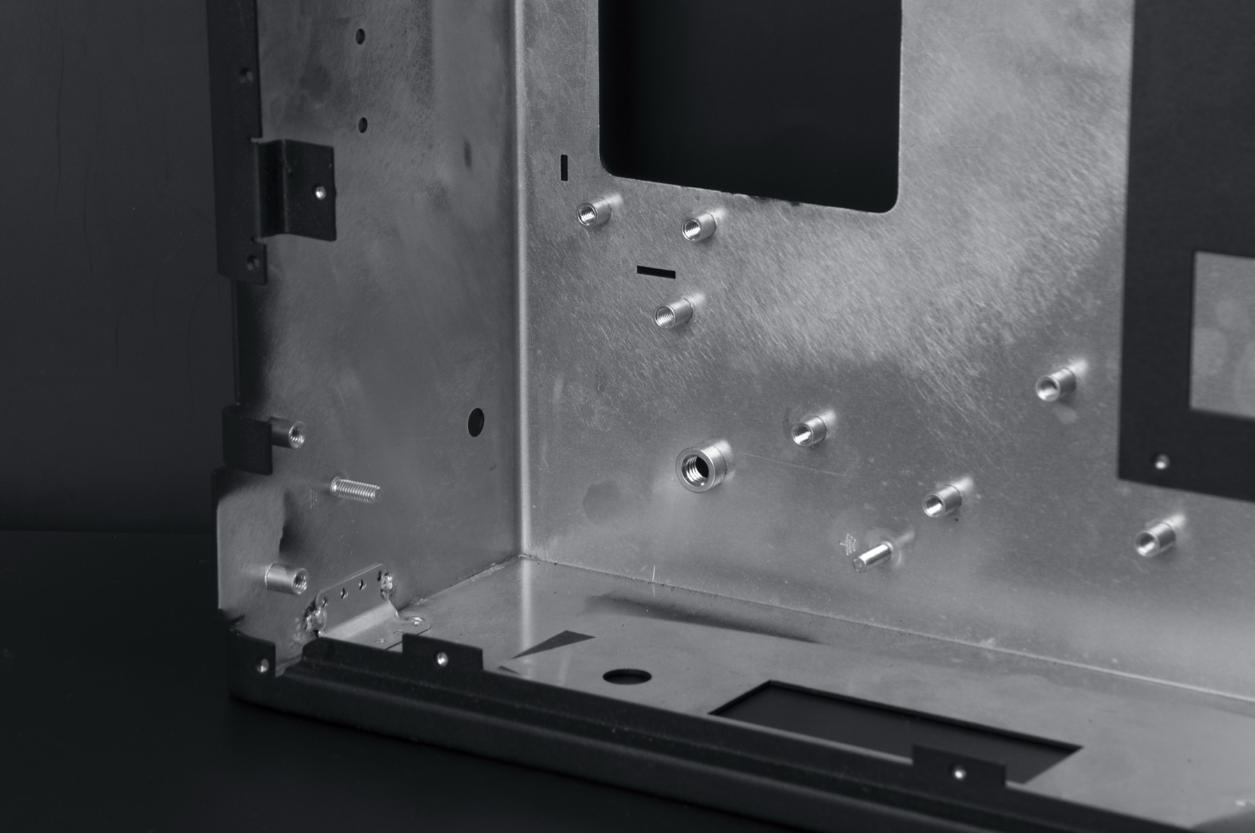
Stainless bracket · Laser cutting, deburring and bending · Flat and post-bend dimensional inspection supported rapid prototype revisions.
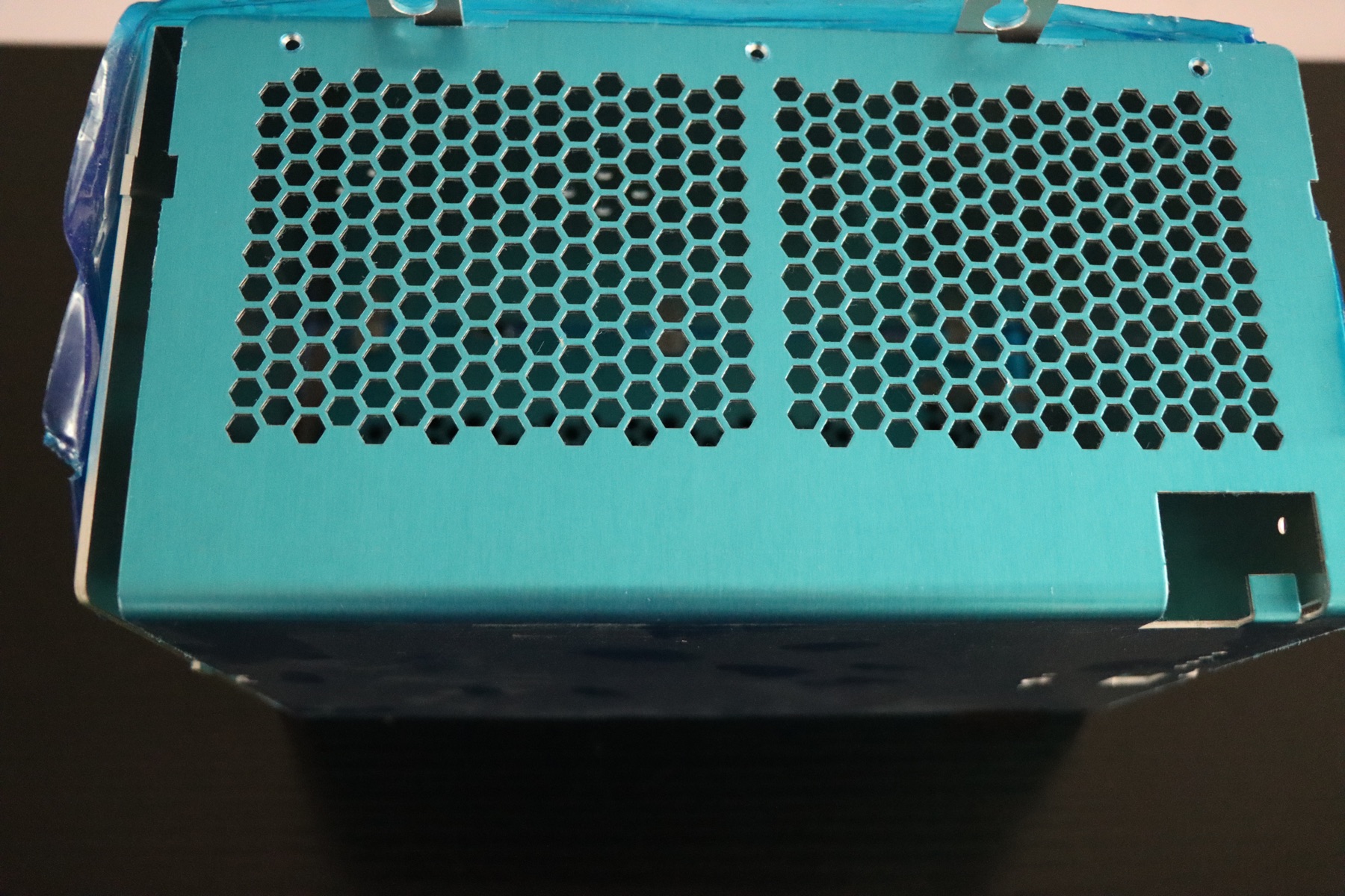
Aluminum panel · Laser cutting, bending and hardware installation · Connector openings and assembly fit controlled without profile tooling.
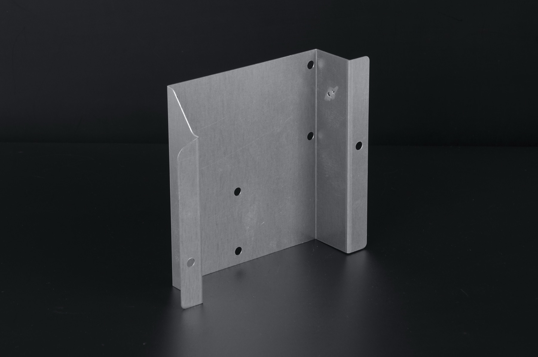
Carbon steel component · Cutting, bending, welding and powder coating · Final mounting geometry verified after finishing.
DXF or DWG files work well for flat geometry. For formed or assembled parts, also provide a 3D model and dimensioned drawing with material, thickness, quantity, finish and critical tolerances.
Carbon steel, stainless steel, aluminum, galvanized steel, copper and brass are available. Thickness depends on material, geometry and edge-quality requirements.
General tolerances are typically ±0.10–0.20 mm. Selected critical features may reach ±0.05 mm after engineering review.
Yes. Its significance depends on the material, thickness, edge requirement and final application.
Yes. Parts can continue into bending, welding, hardware installation, finishing and assembly through one manufacturing route.
Laser cutting offers flexibility without profile tooling; stamping becomes more economical when sustained volume justifies dedicated production tooling.
Send your flat geometry, drawing, material, thickness, quantity, finish and critical requirements for review.