
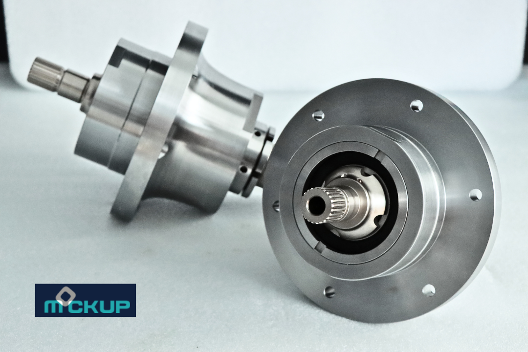
OD Turning & Profiling
Outside diameters, tapers, shoulders, grooves, faces and profiles produced around a controlled centerline.
Get high-precision custom CNC turned parts in metal and plastic for prototypes, low-volume builds and repeat production. Mockup combines fast quoting, engineering review, controlled manufacturing and project-specific inspection evidence in one accountable workflow.
STEP, STP, X_T, SLDPRT, IGES, PDF and ZIP · Confidential handling
CNC turning is a subtractive manufacturing process in which bar, tube or billet stock rotates while computer-controlled tools create concentric outside and inside diameters. It is the direct process for shafts, pins, bushings, sleeves, threaded bodies and circular housings, while live tooling can add flats, slots and cross-holes in the same production route.
ROTATING WORKPIECE / CONTROLLED OD & ID MACHININGCNC turning is usually the efficient choice when the part is built around a central axis. The workpiece rotates while controlled cutting tools create diameters, shoulders, faces, bores, grooves and threads. For off-axis holes, flats or slots, live tooling or a mill-turn route may reduce setups and protect feature relationships.
The turning route is selected from geometry, access, tolerance relationships, production volume and total process risk—not from a generic machine list.
Outside diameters, tapers, shoulders, grooves, faces and profiles produced around a controlled centerline.
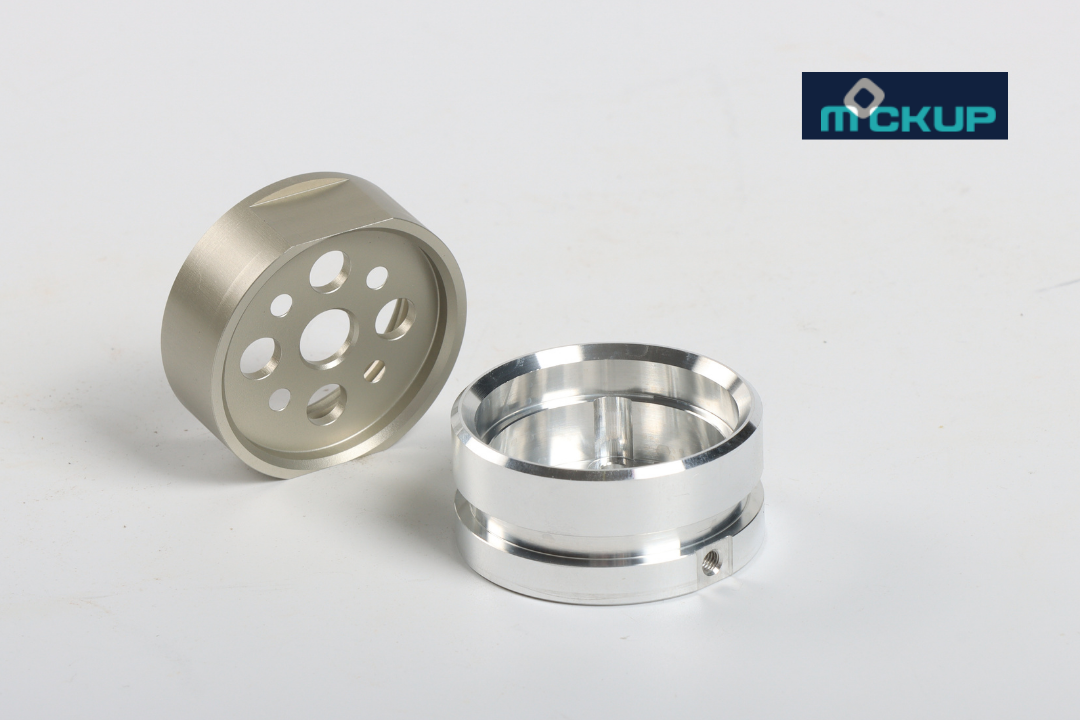
Drilling, boring, reaming and internal grooving for controlled bores, seats and flow paths.
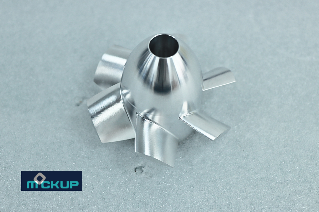
Internal and external threads, undercuts, reliefs, knurls and application-specific forms defined by the drawing.
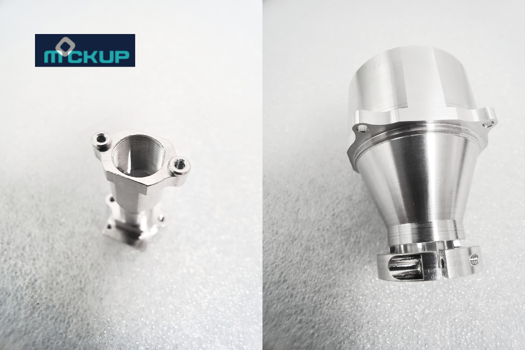
Flats, cross-holes, slots and bolt patterns added with live tooling or a planned secondary milling operation.
Part geometry, material, length-to-diameter ratio, wall thickness, feature access and inspection method affect the practical limit. These values are routing guides; the approved drawing and project review define the commitment.
Maximum turning diameter
500 mm
Maximum turning length
1,500 mm
Minimum practical diameter
1 mm; smaller features by engineering review
Standard dimensional tolerance
ISO 2768-m for untoleranced dimensions
Tighter tolerances
Down to ±0.002 mm on selected features after geometry, material and inspection review
Threads
Metric and imperial; class and gauges confirmed from drawing
Surface roughness
Ra 0.8 μm standard as-turned target; down to Ra 0.4 μm on selected surfaces
Typical quantities
1–10,000+ parts; prototype through repeat production
Documentation
Inspection report, material documentation and CoC as agreed
Every turning project follows a controlled four-stage path so requirements, revisions, manufacturing decisions and acceptance evidence stay connected.
Define — review the model, drawing, material, quantity, target date, critical features and quality evidence
Route — select standard turning, live-tool turning, mill-turn or a combined process around access, setup risk and cost
Make — connect approved requirements and revisions to material, tooling, in-process checks and secondary operations
Verify — inspect against the agreed drawing and preserve project-specific reports, material records and dispositions
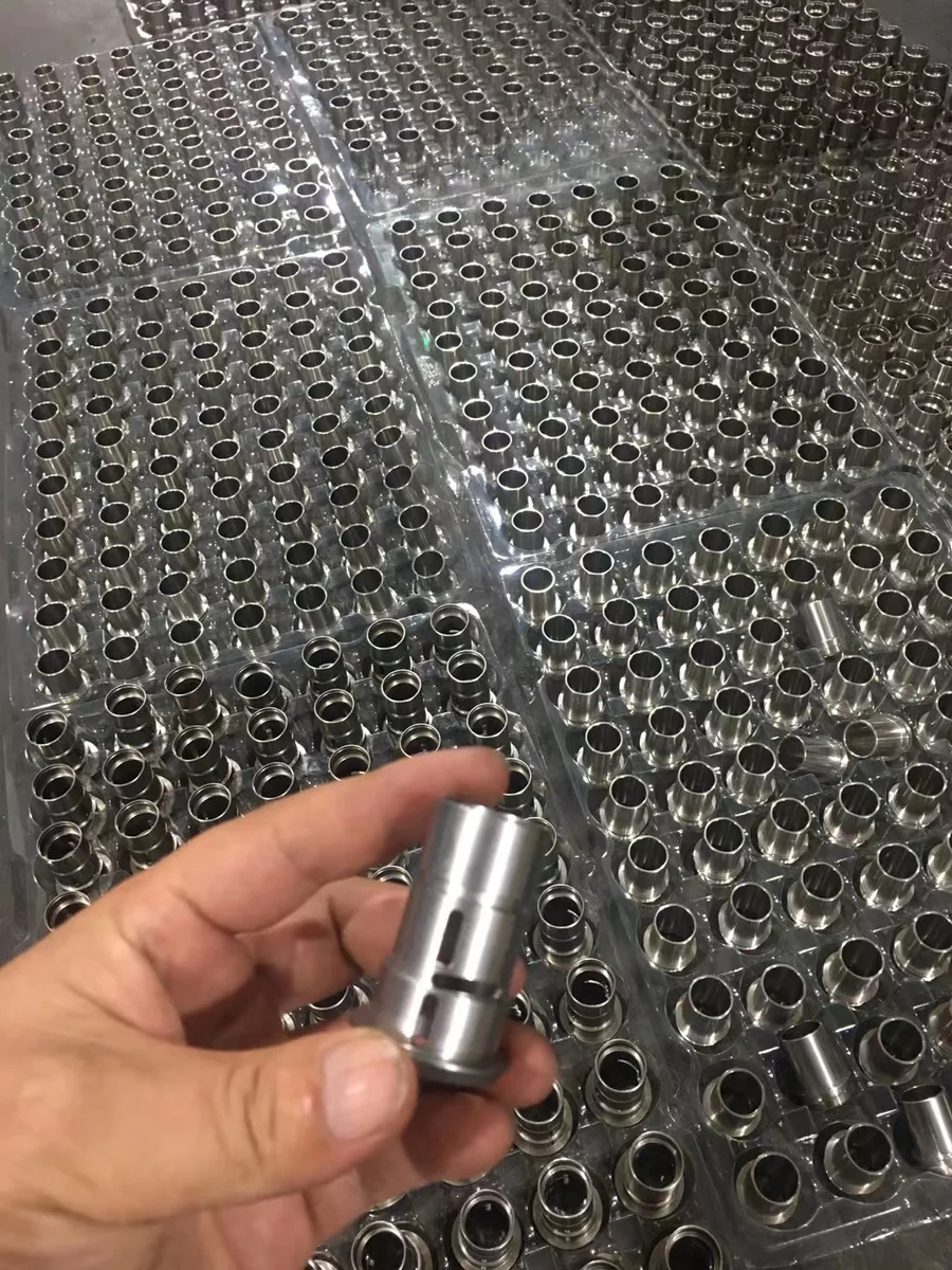
A turned component can meet individual dimensions and still fail at assembly if concentricity, runout, thread fit, surface condition or datum relationships are misunderstood. Mockup connects the acceptance plan to the drawing before machining begins.
Mockup turns common metals and engineering plastics for prototypes and production parts. Availability, certification, temper, condition and substitute rules are confirmed for each project.
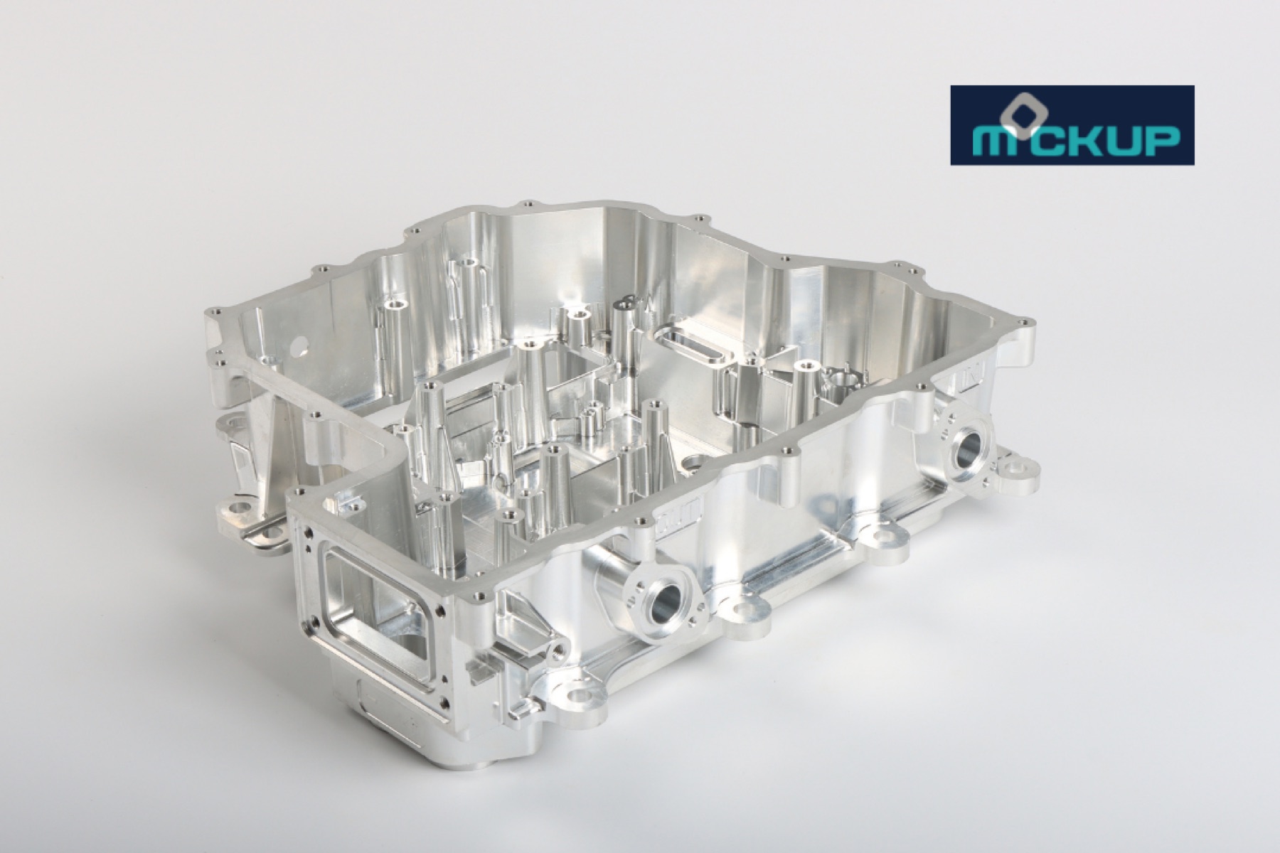
Secondary finishing can change appearance, corrosion resistance, wear behavior and dimensions. Masking, coating thickness, cosmetic zones and post-finish tolerances are defined before the route is approved.
Metals and engineering plastics
Natural toolpath appearance
Define Ra only on functional surfaces
Aluminum alloys
Clear, black or specified colors
Protect threads and account for coating buildup
Stainless steels
Natural metallic appearance
Confirm specification and documentation requirement
Ferrous alloys
Dark conversion finish
Define corrosion expectation and oil or seal requirement
Compatible metals
Uniform plated appearance
Account for thickness on fits and threads
Process-compatible metals
Matte, directional or bright
Define visual standard and protect functional surfaces
Compatible substrates
Specified color and texture
Define masking and coating build
Turning DFM should protect functional relationships while removing avoidable setup, tooling and measurement difficulty.
Use a clear datum scheme — dimension related diameters and faces from functional references
Call out only functional tight tolerances — identify the fit or performance requirement behind them
Control slender and thin-wall features — share load, sealing or weight constraints for route review
Specify threads completely — include standard, size, pitch, class, depth and gauge requirements
Plan off-axis features intentionally — flats, cross-holes and slots may favor live tooling or secondary milling
Separate cosmetic and functional surfaces — mark visible areas, tool marks, finish direction and protected surfaces
Representative turned-part programs demonstrate how the manufacturing route and inspection method are selected around function without exposing customer IP.
316 stainless steel · turning + bore finishing · fit and concentricity verified by bore gauge and CMM report.
6061-T6 aluminum · turning + cross-hole milling · sealing diameter and port position verified by CMM.
4140 alloy steel · turning + heat treatment + grinding · runout and bearing seats verified after final processing.
Upload the model, drawing and project context. A manufacturing engineer will review the turning route, critical requirements, inspection plan and documentation needs before the project moves forward.
Get an online CNC turning quote↗STEP / STP / PARASOLID + PDF DRAWING RECOMMENDEDParts organized around a central axis—such as shafts, pins, bushings, sleeves, spacers, fittings and collars—are usually strong candidates. Designs with flats, radial holes or slots may use live tooling or a combined mill-turn route.
In turning, the workpiece rotates while tools shape cylindrical and rotational features. In milling, the cutting tool rotates around a generally stationary workpiece to create prismatic faces, pockets and multi-sided geometry. Some parts use both processes.
Yes. Selected features can be reviewed down to ±0.002 mm. The final commitment depends on material, geometry, feature relationships, setup and measurement method and is confirmed against the approved drawing.
Yes. Live-tool and combined machining routes are available for axial or radial holes, flats, slots and milled features. Route selection depends on access, tolerance relationships, quantity and setup risk.
Yes. Mockup supports quantities from one prototype through 10,000+ repeat-production parts, with routing, tooling, revision control and inspection planning adjusted to the release pattern.
Send a 3D CAD model plus a dimensioned drawing whenever tolerances, threads, surface finish, material condition or inspection requirements matter. Include quantity, target date and required reports.
Project-specific deliverables may include dimensional inspection results, first-article data, material documentation and a certificate of conformity. Scope and sampling are confirmed during review.
The approved model, drawing revision, manufacturing decisions, quality requirements and agreed changes remain connected to the project record, giving repeat production a controlled starting point.
Upload the model, drawing and project context. Tell us which dimensions, fits, surfaces or documents determine acceptance.