
Insert and interface DFM
Review retention geometry, shutoffs, loading access, stress concentration and realistic molding tolerances before steel is cut.
EXPLOREMold engineered plastic around metal inserts, contacts or structural elements to consolidate assembly and create durable mechanical and electrical interfaces.
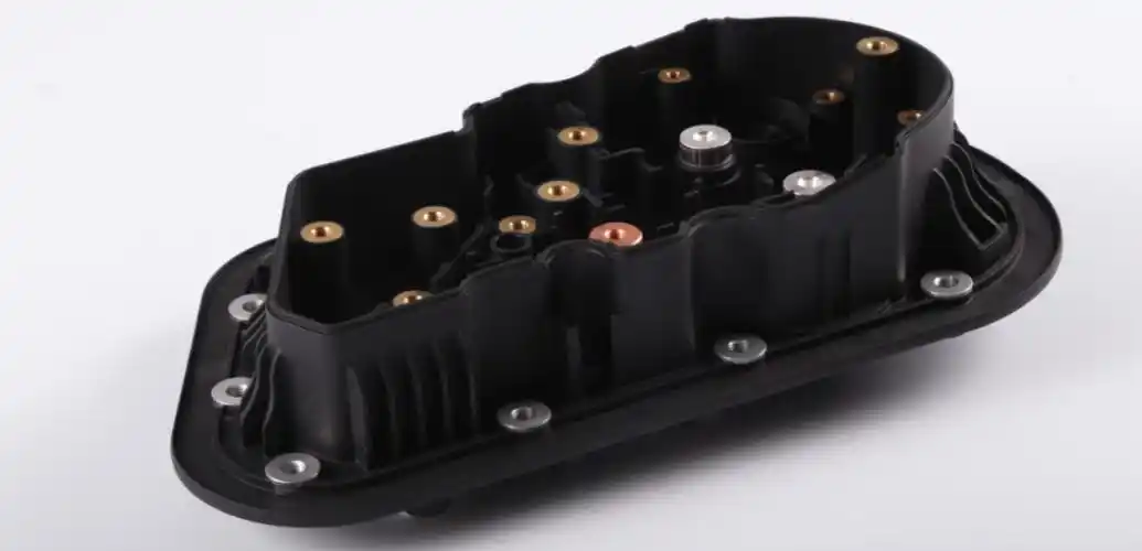
Insert molding combines a preformed component—commonly a threaded insert, terminal, pin or structural element—with injected thermoplastic in one molding cycle. Success depends on insert retention, location, shutoff design, resin flow, thermal behavior and a loading method matched to volume.
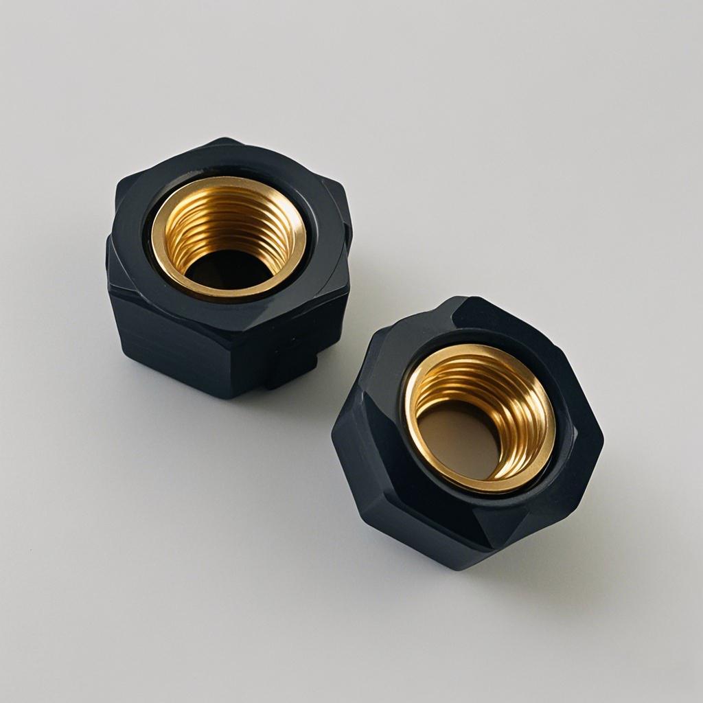
Review retention geometry, shutoffs, loading access, stress concentration and realistic molding tolerances before steel is cut.
EXPLORESelect an aluminum or steel tooling route around quantity, validation needs, insert handling and expected tool life.
EXPLOREAlign resin grade, metal alloy, plating and insert specification with heat, chemicals, electrical and mechanical loads.
EXPLOREBuild a practical plan for position, pull-out, torque, continuity, dimensions and project-specific functional evidence.
EXPLORE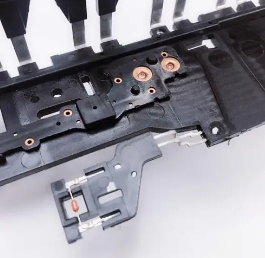
Integrate brass or steel inserts where repeated fastening, service access or higher pull-out strength is required.
Mold around terminals, pins and conductive elements while protecting alignment and required isolation distances.
Capture metal frames, bushings or load-bearing features inside a molded housing or mechanism.
Replace selected post-mold fastening, staking or adhesive steps with an integrated molded interface.
Capture tubes, fittings or precision features where leak paths and dimensional relationships require controlled validation.
Integrate small functional elements into housings and mechanisms with traceable materials and inspection planning.
Explore common starting points. Final grade selection is confirmed against geometry, environment, compliance and the intended production process.
A practical starting point for housings and mechanisms needing balanced stiffness, appearance and processability.
An operator places each insert into positive mold location features before the cycle. The tool and work instructions are designed to prevent reversed, missing or double-loaded inserts.
Best fitPrototypes, bridge production, larger inserts and programs where product revisions are still possible.
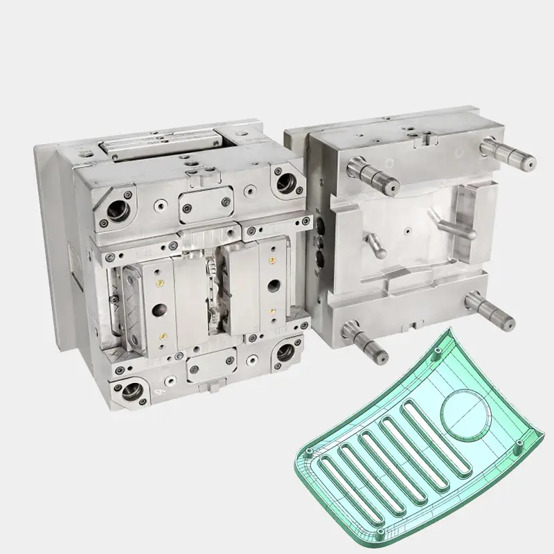
Review knurls, grooves, undercuts and shoulder geometry against pull-out and torque requirements.
Define orientation, tolerance, mistake-proofing and manual or automated loading before tool design is released.
Consider resin processing temperature, insert coating, corrosion risk, thermal expansion and stress around the interface.
Control resin flow around the insert while protecting threads, contacts and surfaces that must remain exposed.
Balance local plastic thickness, knit lines and radial stress to reduce cracking, sink and inconsistent retention.
Agree insert position, torque, pull-out, electrical or dimensional checks based on functional risk.
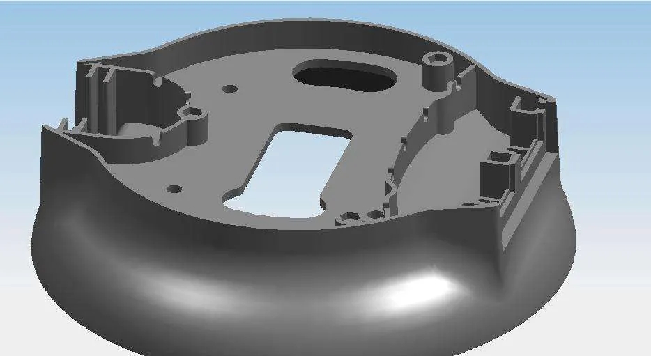
Confirm 3D geometry, drawing requirements, insert specification and functional loads.
Review retention, shutoffs, gate strategy, venting, ejection and insert loading access.
Manufacture the tool, sample production-intent materials and document findings.
Verify insert location, molded geometry, interface performance and agreed inspection evidence.
Maintain approved inserts, resin, process settings, revision and inspection records.
Inspection is planned around the interface and the failure modes that matter—not added as a generic checklist after sampling.
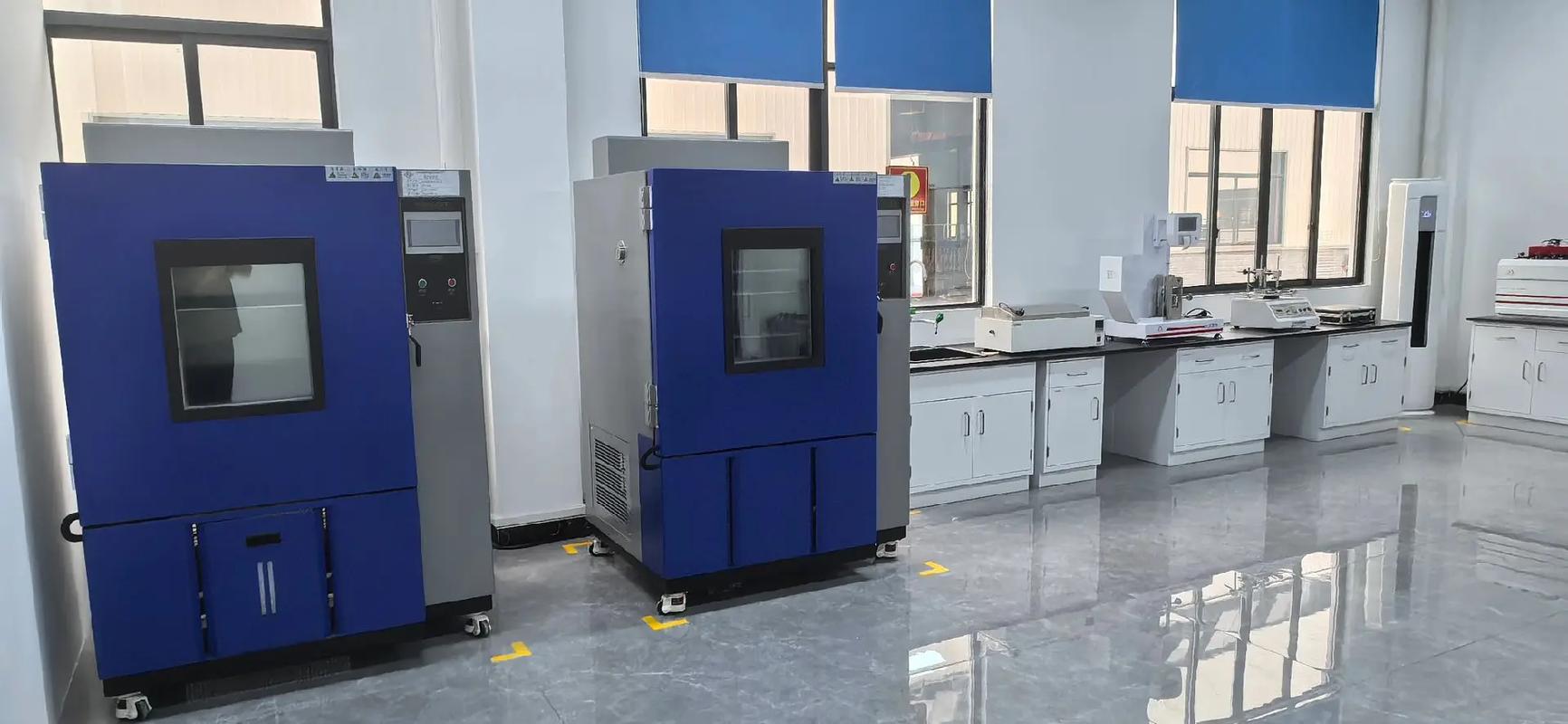
Visual, fixture, vision or dimensional checks confirm that every insert is present, oriented and within the agreed location envelope.
Project-specific destructive testing validates the mechanical interface rather than relying only on molded appearance.
FAI, layout inspection and in-process checks focus on datum relationships, exposed features and mating geometry.
Continuity, isolation, pressure decay or other functional tests can be planned where the application requires them.
Common examples include threaded inserts, bushings, terminals, pins, contacts and structural metal elements. The exact insert and loading method are reviewed against geometry, resin and volume.
The mold uses locating and support features designed around the insert. Retention must withstand mold closing, resin pressure and part ejection without damaging controlled surfaces.
Yes, when insert geometry, orientation, production quantity and business case support automation. Manual loading may remain practical for prototypes and lower-volume programs.
Depending on the application, inspection may include position checks, torque, pull-out, push-out, electrical continuity or project-specific functional tests.
Insert molding can reduce downstream assembly and improve integration, while post-mold insertion may simplify tooling or reduce insert exposure to molding heat. We compare total program risk, volume and service loads.
Yes. The drawing, material, plating, packaging, cleanliness and lot-traceability requirements should be agreed before sampling.
Share the model, drawing, materials, expected quantity and functional requirements. Engineering will identify the decisions needed before tooling release.
Attach at least one CAD file or drawing for review in context.