ADDITIVE MANUFACTURING · POLYMER · METAL · PROCESS REVIEW

Custom 3D Printing Services for Prototypes and Production Parts

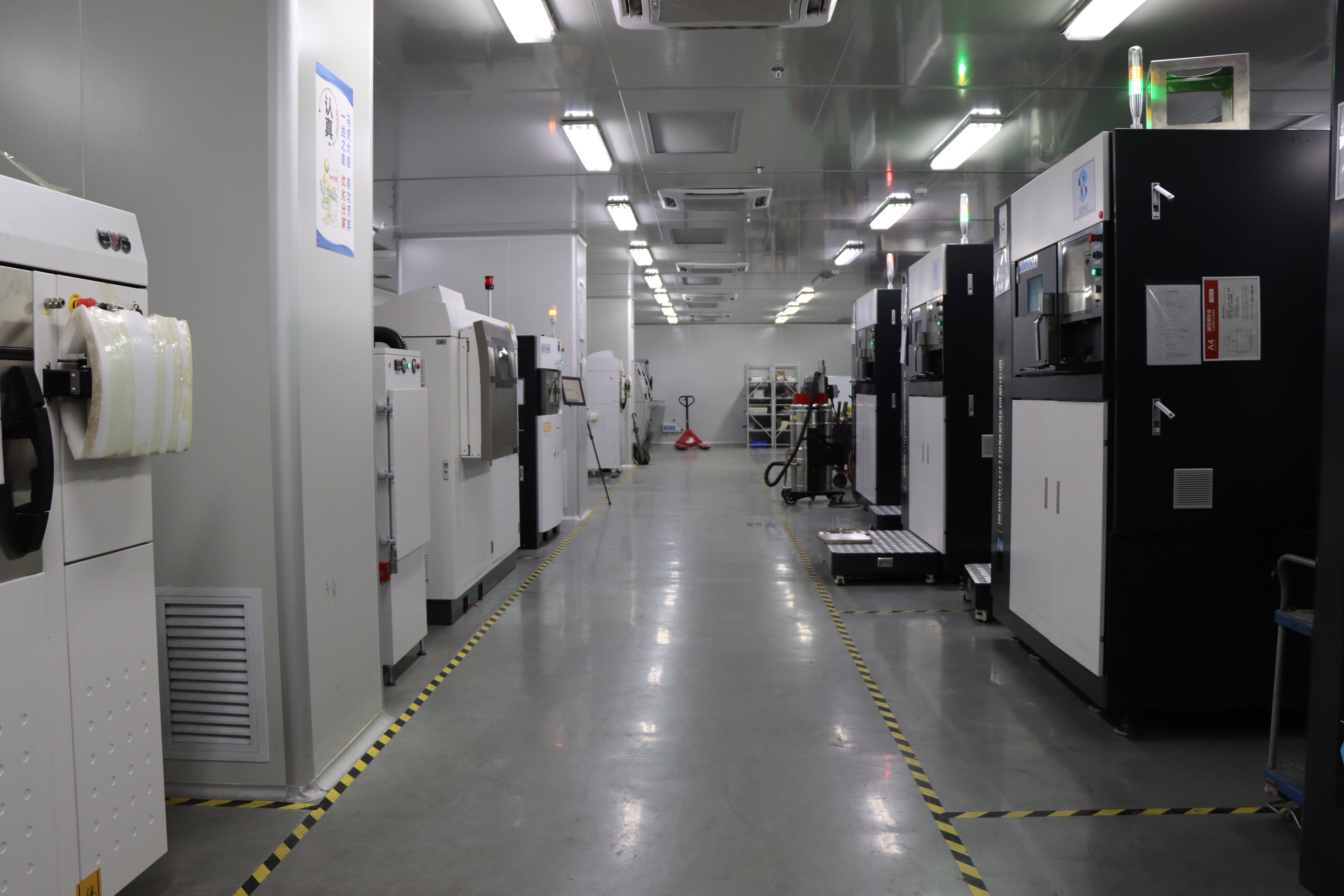
Turn a digital model into physical parts without investing in dedicated molds or production tooling. Mockup provides online 3D printing services for visual prototypes, functional testing, engineering validation, bridge production and low-volume end-use parts. We coordinate SLA, SLS, MJF, FDM and metal additive manufacturing according to what your part actually needs to achieve—not simply which machine can print the geometry. Our engineers review part size, geometry, material behavior, feature detail, mechanical requirements, surface expectations, quantity and downstream operations before recommending a manufacturing route. When the printed condition is not enough, Mockup can coordinate secondary operations such as sanding, polishing, dyeing, painting, heat treatment, inserts, threading and CNC machining.

  • 5 additive manufacturing technologies
  • Polymer and metal material options
  • One-off prototypes through low-volume production
  • Secondary finishing and machining available
  • Inspection planned around drawing requirements

Encrypted upload · Confidential handling · Engineer review

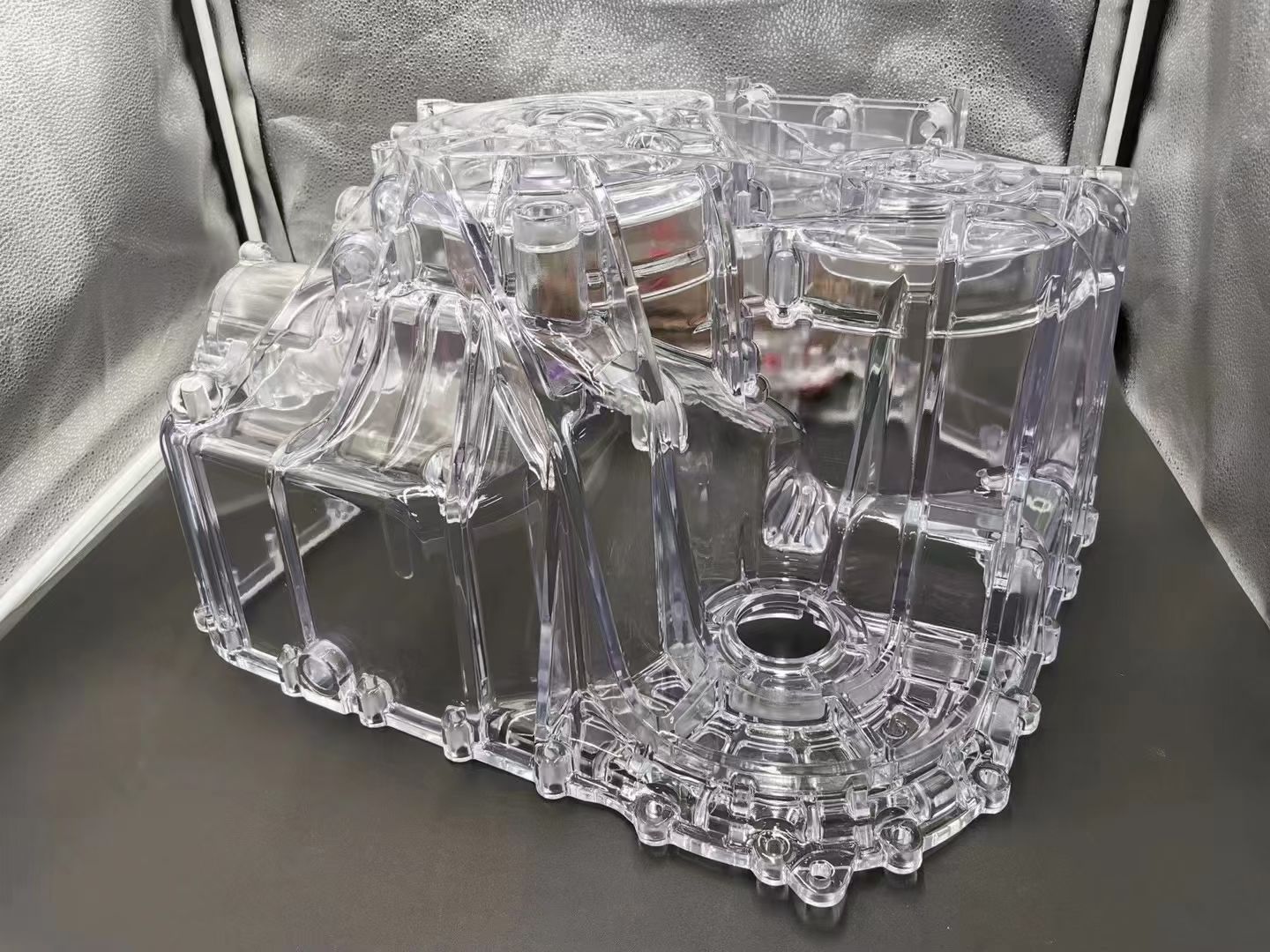
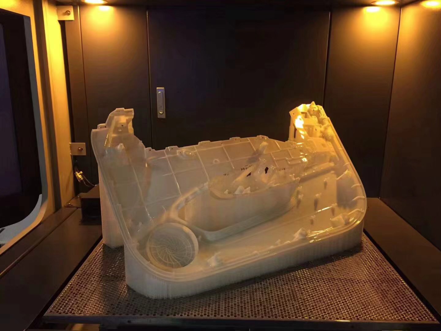
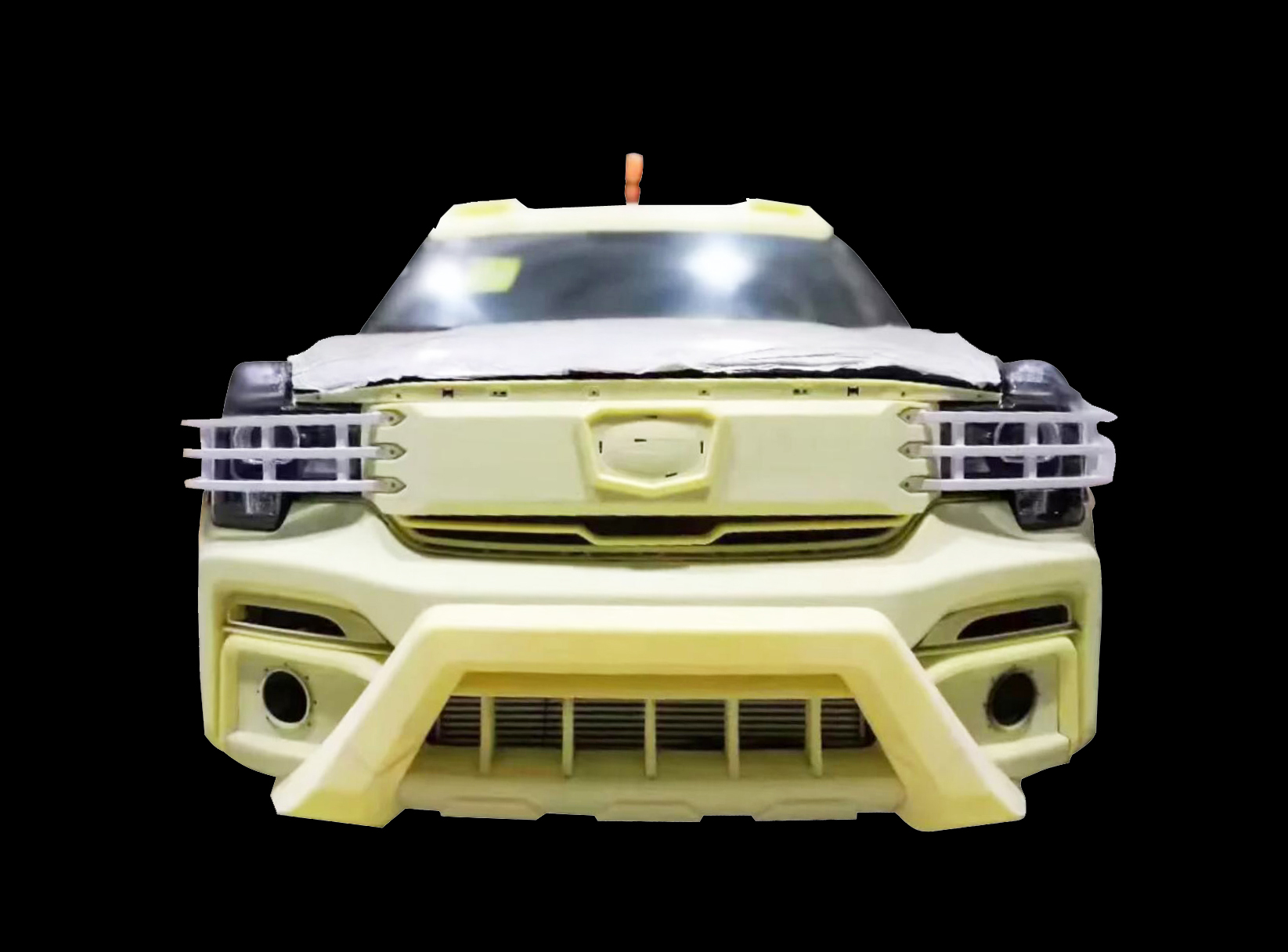
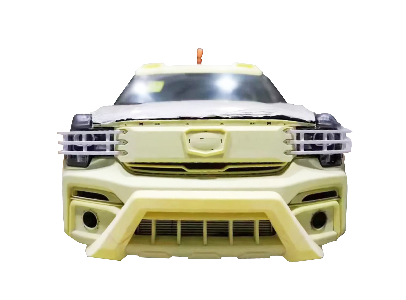
3D PRINTING / PROCESS REVIEWLarge SLA 3D printed automotive prototype
DIGITAL MODEL / PHYSICAL EVIDENCE
AVAILABLE ROUTES5 PROCESSESPOLYMER + METAL
5ADDITIVE TECHNOLOGIES
1 → BATCHPROTOTYPE TO PRODUCTION
DFAMENGINEERING REVIEW
QADRAWING-LED INSPECTION
PROCESS BEFORE MACHINE

Choose the route around what the part must prove.

Mockup reviews appearance, mechanical behavior, geometry, quantity, post-processing and inspection before recommending SLA, SLS, MJF, FDM, metal additive manufacturing or another suitable route.

01 / 3D PRINTING

3D Printing Capabilities at a Glance

Different additive technologies solve different manufacturing problems. A process that produces an excellent visual model may be the wrong choice for a functional nylon housing. A process optimized for nested production quantities may provide unnecessary complexity for a single concept model. Mockup evaluates the complete requirement before production. The final route is confirmed after reviewing the CAD model and functional requirements.

CapabilityAvailable Route
Visual prototypesSLA / FDM depending on requirement
High-detail prototypesSLA
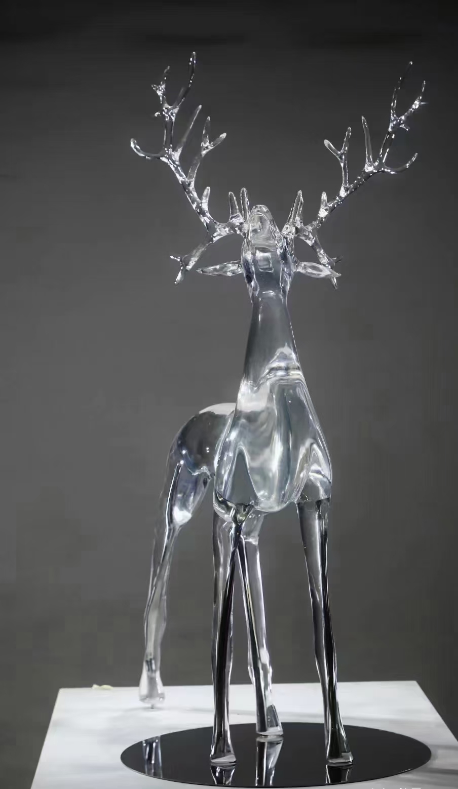
Clear or translucent partsSLA with suitable resin and finishing
Functional nylon partsSLS / MJF
Complex support-free polymer geometrySLS / MJF
Large economical prototypesFDM
Jigs and fixturesFDM / SLS / MJF
Flexible polymer partsTPU-compatible processes
Low-volume productionSLS / MJF / selected SLA and FDM routes
Complex metal partsMetal additive manufacturing
Precision interfacesPrinting + CNC post-machining
Cosmetic finishingAvailable according to process and material
InspectionDrawing- and application-specific
02 / 3D PRINTING

Choose the 3D Printing Process by What the Part Must Prove

The right process depends on the engineering question behind the part. Does the prototype need to look like the final product? Survive assembly testing? Carry a mechanical load? Demonstrate an internal flow path? Validate ergonomics? Or function as a repeatable production component? These requirements should drive process selection.

01 / ADDITIVE

SLA 3D Printing

Fine Detail and Smooth Prototype Surfaces. Stereolithography, or SLA, uses a light source to selectively cure liquid photopolymer resin. SLA is particularly useful when visual quality, fine features and surface detail matter more than production-like thermoplastic behavior. Best suited for: SLA parts typically require support structures. After printing, parts are cleaned, supports are removed and the resin is post-cured. Additional sanding, polishing, painting or clear finishing can improve cosmetic surfaces. Clear components may require substantial finishing when high transparency is expected. Photopolymer properties vary significantly by resin. An “ABS-like” or “PC-like” marketing description should not be interpreted as identical to injection-molded ABS or polycarbonate. Select the resin according to actual mechanical, thermal and environmental requirements. Best suited for: Appearance models · High-detail prototypes · Presentation models · Clear and translucent components · Small detailed housings · Form-and-fit evaluation · Master patterns · Casting masters · Fluidic models · Cosmetic prototypes
TYPICAL PARTS
Appearance models · High-detail prototypes · Presentation models · Clear and translucent components · Small detailed housings · Form-and-fit evaluation · Master patterns · Casting masters · Fluidic models · Cosmetic prototypes
PROGRAM NOTES
Mockup additive manufacturing / engineer reviewed
SLA 3D Printing
MOCKUP / APPLICATIONSSLA 3D Printing
03 / 3D PRINTING

From Prototype to Production

3D printing can support several stages of product development, but each stage places different demands on the manufacturing process.

0101 / ADDITIVE

Concept Models

Early prototypes help teams evaluate size, proportion, ergonomics and design direction before committing to detailed engineering or tooling. At this stage, speed and cost may matter more than final mechanical properties. SLA and FDM are frequently useful depending on model size, appearance requirements and required detail.

0202 / ADDITIVE

Visual and Presentation Prototypes

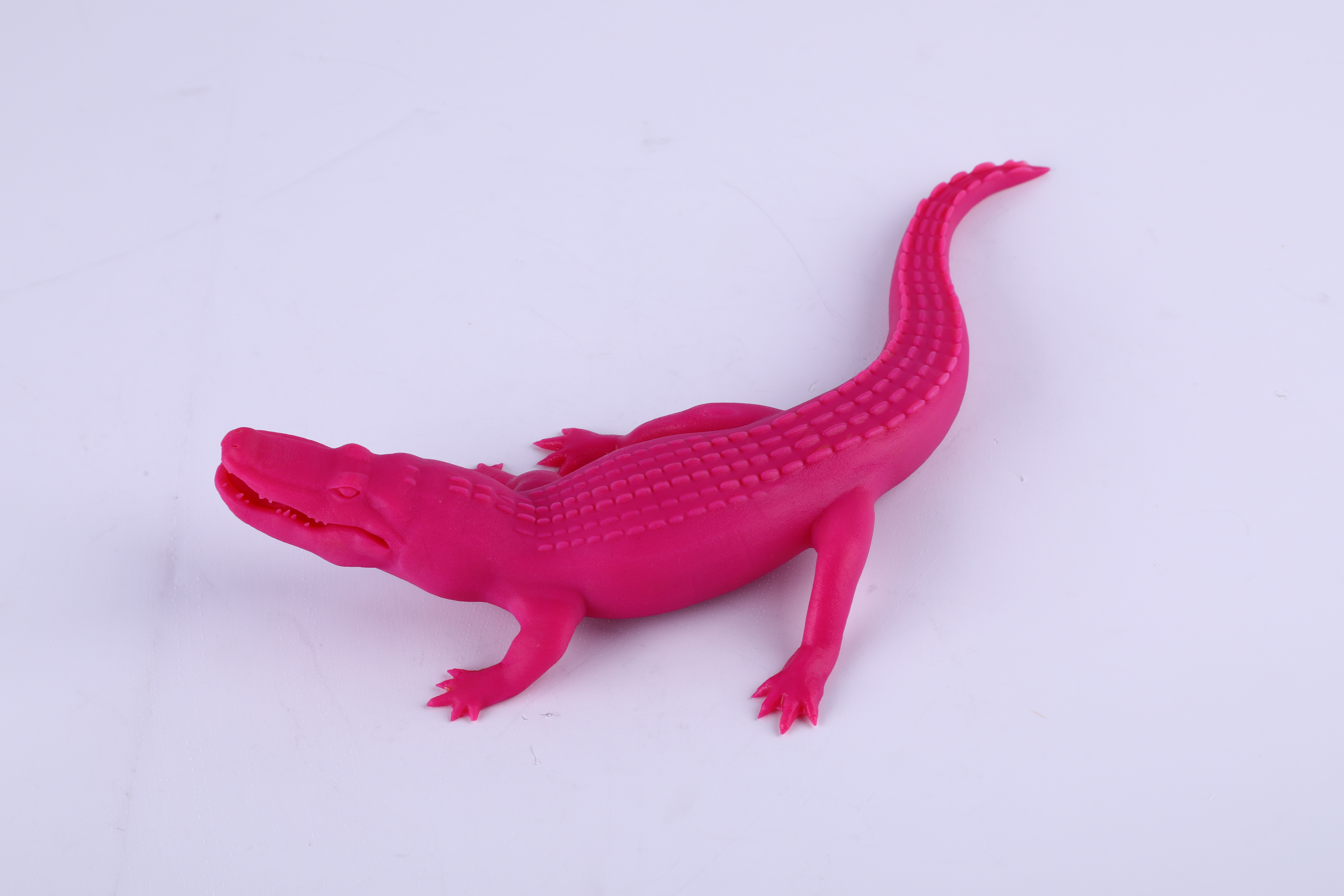
A prototype intended for customer review, photography, investor presentation or design approval may require much more than dimensional geometry. Surface smoothness, color, transparency and assembly appearance can become primary requirements. SLA combined with sanding, polishing, painting or clear finishing is often appropriate for this type of work.

0303 / ADDITIVE

Functional Prototypes

Functional prototypes answer engineering questions. They may be used to evaluate: Material and process selection should reflect the property being tested. A visually accurate prototype is not automatically mechanically representative of the future molded or machined component. Best suited for: Fit · Assembly · Snap features · Ergonomics · Airflow · Fluid routing · Mechanical movement · Installation · Cable routing · Basic loading · Thermal behavior

0404 / ADDITIVE

Engineering Validation

As the design matures, dimensional control and documentation become more important. Critical dimensions should be identified on a drawing rather than assumed from the CAD model. The project may also require defined build orientation, material records, inspection reports or controlled post-processing.

0505 / ADDITIVE

Bridge Production

3D printing can supply market-entry, pilot, service or pre-tooling quantities without hard tooling. This is particularly useful when: SLS and MJF can be especially useful for polymer bridge production because multiple components can be nested within one build. Best suited for: Tooling is still being manufactured · Product demand is uncertain · Design changes remain possible · Multiple variants are required · Initial production quantity is limited · Replacement parts are needed

0606 / ADDITIVE

Production Parts

Additive manufacturing can also produce end-use components when the process and material meet application requirements. Production use requires more disciplined consideration of: The decision should be based on the intended use rather than the assumption that every printable material is automatically production-ready. Best suited for: Material properties · Orientation · Repeatability · Post-processing · Surface condition · Dimensional control · Traceability · Inspection · Environmental exposure · Qualification requirements

04 / 3D PRINTING

SLA vs SLS vs MJF vs FDM vs Metal 3D Printing

No single technology provides the best combination of cost, strength, accuracy, surface quality and lead time. Mockup selects the process according to the requirements that matter most to the part.

COMPARE5 additive routes
SLA 3D printing exampleSLASLS 3D printing exampleSLSMJF 3D printing exampleMJFFDM 3D printing exampleFDMMetal AM 3D printing exampleMetal AM
Primary strength

Fine detail and cosmetic quality

Complex functional polymer parts

Consistent functional batches

Economical and scalable part size

High-value geometric complexity

Surface & detail

Excellent detail; smooth surfaces possible

Matte / grainy

Fine matte

Visible layer structure

Process-dependent; finishing often required

Supports

Required

Not normally required

Not normally required

Often required

Usually required

Typical materials

Photopolymer resins

PA11, PA12, filled nylons

PA12, PA11, TPU and selected materials

Engineering thermoplastics

Aluminum, steel, titanium, nickel alloys

Best fit

Appearance, clear and detailed prototypes

Functional prototypes and complex nylon parts

Functional parts and small-batch production

Concepts, fixtures and larger prototypes

Complex metal parts and internal geometry

No single technology provides the best combination of cost, strength, accuracy, surface quality and lead time. Mockup selects the process according to the requirements that matter most to the part.

Ask for a process recommendation
05 / 3D PRINTING

3D Printing Materials

Material selection should start with function rather than a familiar material name. Consider operating temperature, mechanical load, flexibility, UV exposure, chemicals, moisture, surface requirements and expected service life before choosing a material.

01 / ADDITIVE

SLA Photopolymer Resins

Available resin families may include materials designed for: Terms such as ABS-like, PP-like and PC-like describe approximate behavior or positioning. They do not mean the printed photopolymer has the same complete property profile as the corresponding production thermoplastic. Best suited for: General prototyping · Fine-detail models · Clear components · Tough applications · Heat-resistant prototypes · Flexible or elastic behavior · Casting patterns
GRADES / OPTIONS
General prototyping · Fine-detail models · Clear components · Tough applications · Heat-resistant prototypes · Flexible or elastic behavior · Casting patterns
FINISH / NOTES
Mockup additive manufacturing / engineer reviewed
SLA Photopolymer Resins
MOCKUP / MATERIALSSLA Photopolymer Resins
06 / 3D PRINTING

3D Printing Technical Specifications

There is no universal “3D printing tolerance.” Accuracy, minimum wall thickness, feature resolution and surface condition vary substantially between processes and can also change with material, geometry, orientation and part size. For dimensions that directly affect assembly, sealing, bearing location or other functional interfaces, provide a drawing with tolerances and acceptance requirements. Mockup will determine whether those dimensions should remain as printed or require secondary machining.

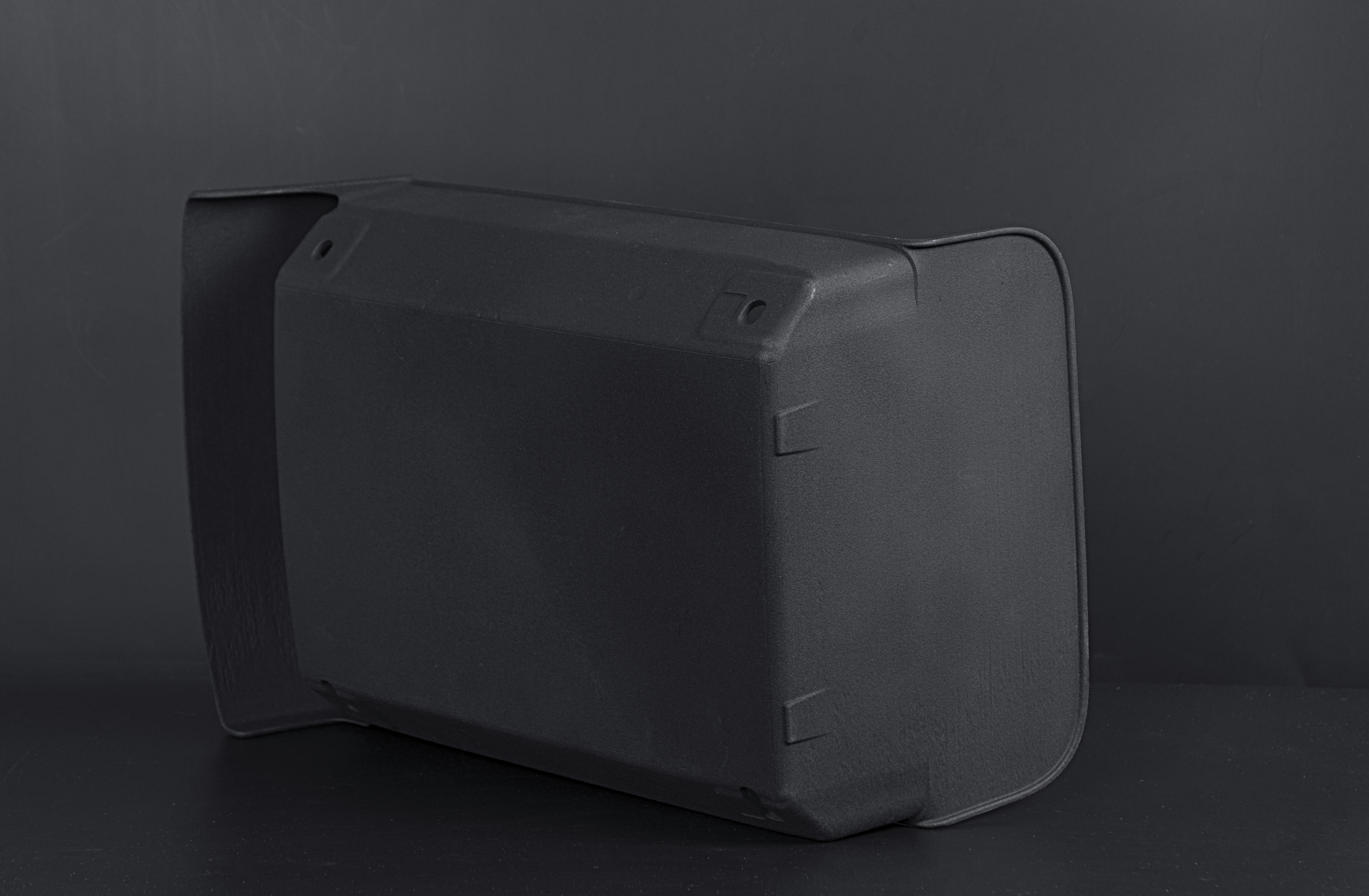
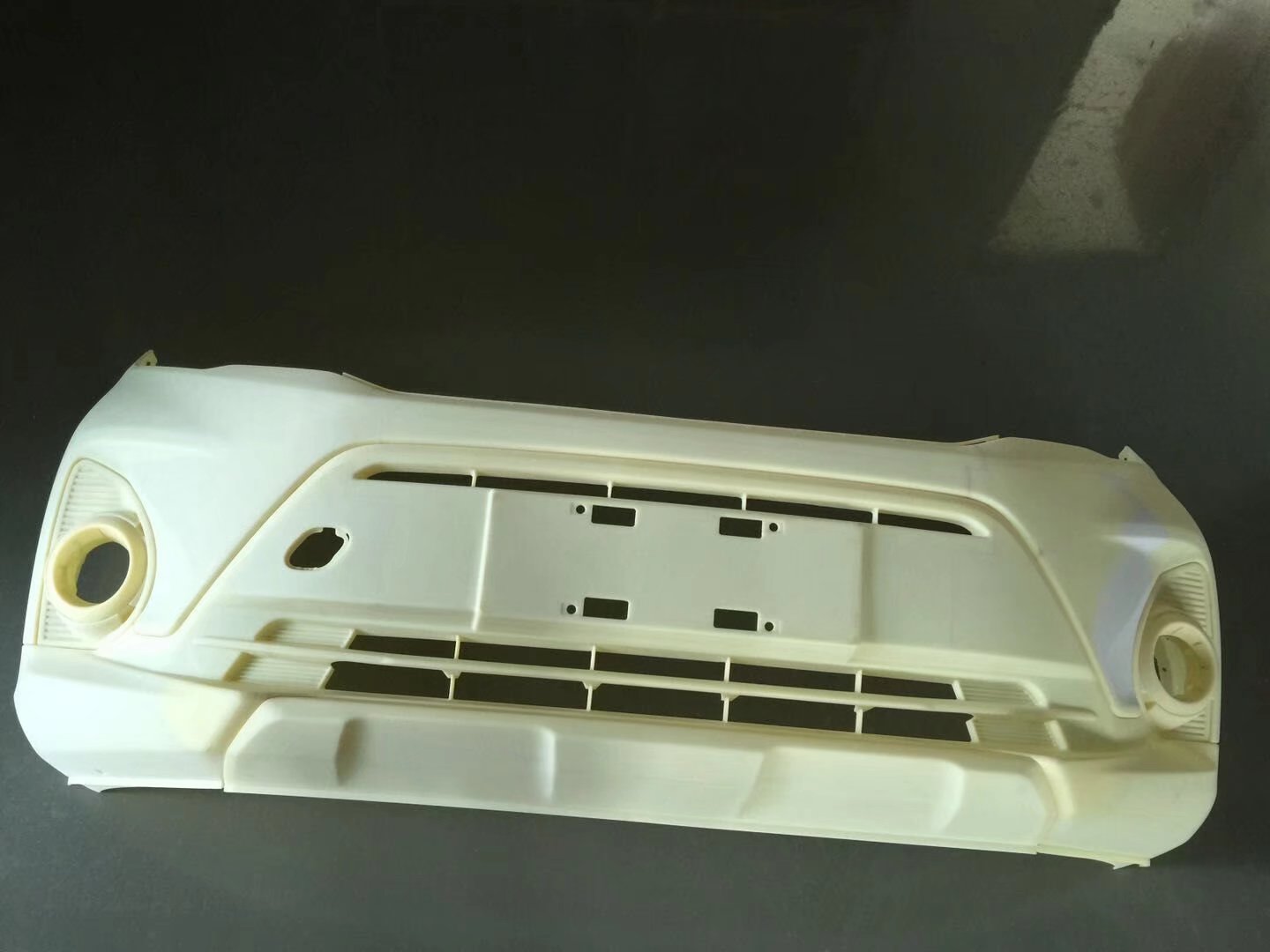
Large format 3D printed prototype
07 / 3D PRINTING

Finishing and Secondary Operations

A printed part does not always represent the finished component. Mockup can coordinate post-processing according to the printing technology, material and intended use.

IMAGEFINISHAPPLICABLE MATERIALSCOLOR / APPEARANCEPROCESS NOTES
Support Removal
Support Removal

SLA, FDM and metal additive parts may require physical support structures during printing. Supports must be removed while controlling damage to adjacent functional or cosmetic surfaces.

Mockup additive manufacturing / engineer reviewed

Bead Blasting
Bead Blasting

Bead blasting can help produce a more uniform matte surface on suitable polymer or metal printed components.

Mockup additive manufacturing / engineer reviewed

Sanding and Polishing

SLA and selected FDM parts can be manually finished to reduce visible build or support marks. Clear SLA components may require progressive sanding, polishing and coating depending on the required transparency.

Mockup additive manufacturing / engineer reviewed

Dyeing
Dyeing

SLS and MJF nylon parts can often be dyed to provide a more uniform appearance. Color consistency and cosmetic acceptance requirements should be agreed before production.

Mockup additive manufacturing / engineer reviewed

Painting and Coating

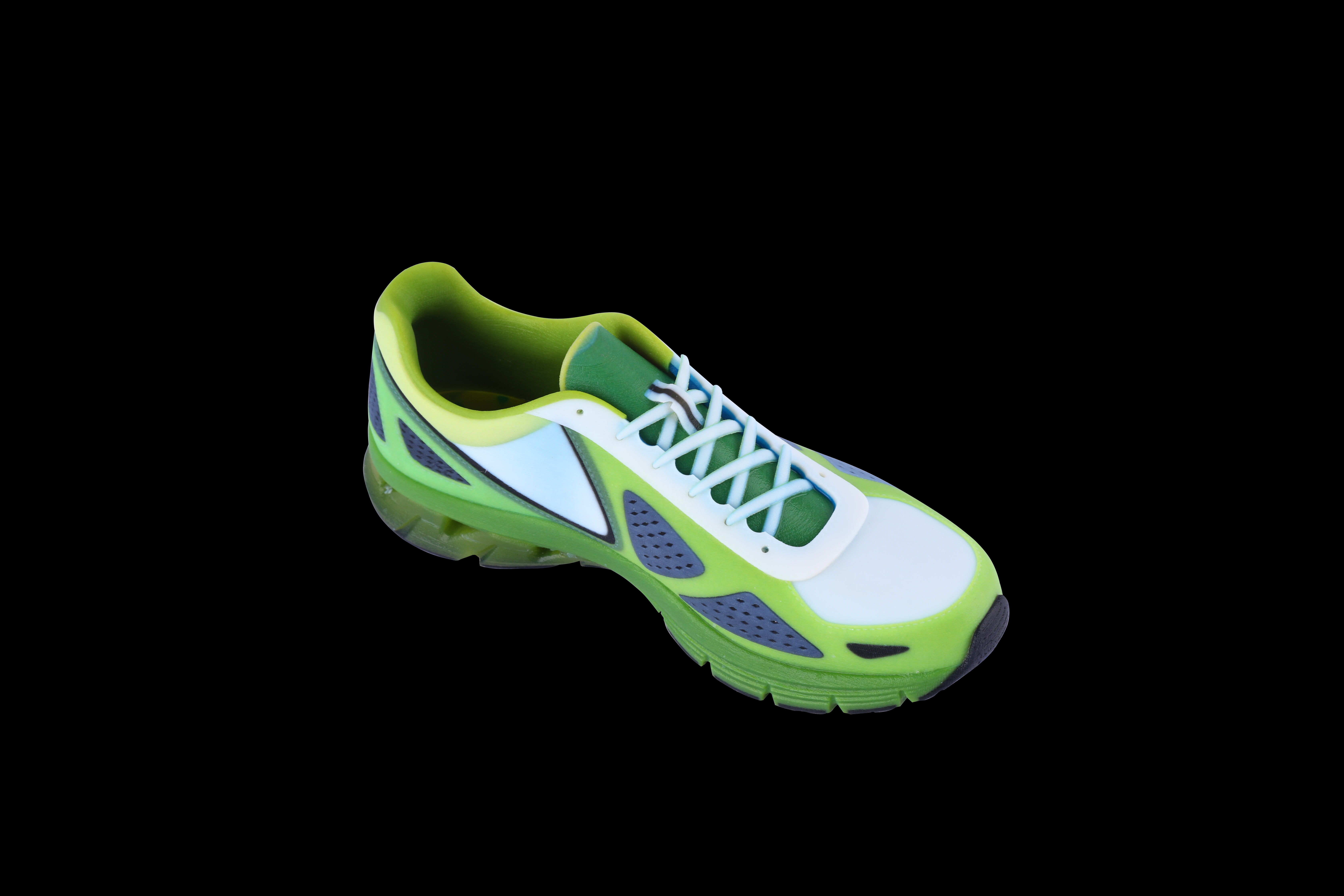
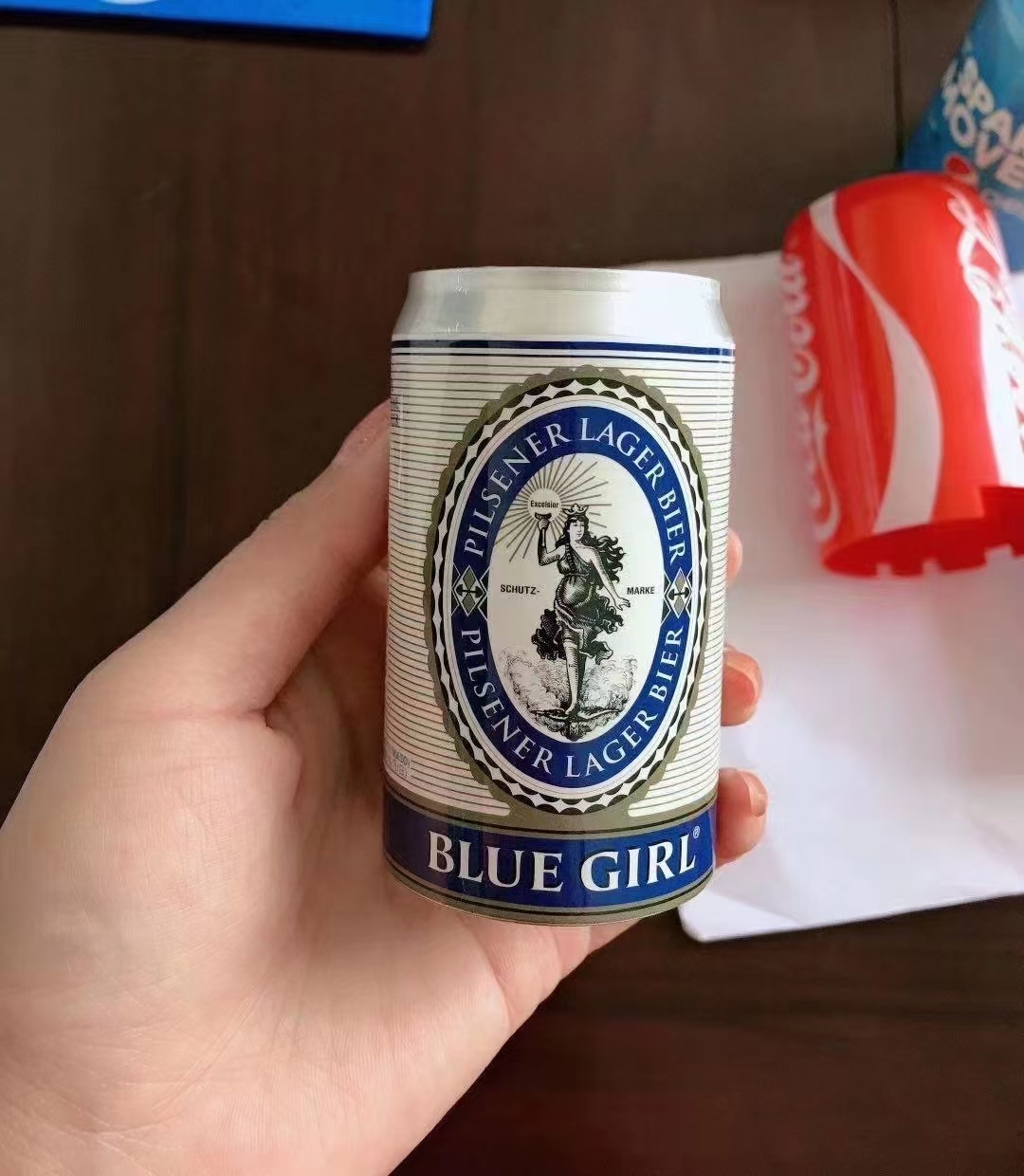
Priming, painting and clear coating can transform a printed prototype into a presentation-quality model. Surface preparation requirements depend on printing process and expected finish.

Mockup additive manufacturing / engineer reviewed

Vapor Smoothing
Vapor Smoothing

Compatible polymer materials may be suitable for controlled vapor smoothing where improved surface appearance or behavior is required. Availability depends on material and project requirements.

Mockup additive manufacturing / engineer reviewed

Inserts and Threading

Threaded inserts can be installed in suitable polymer components when stronger or more durable threaded connections are required. Threads may also be machined or otherwise produced according to material and geometry.

Mockup additive manufacturing / engineer reviewed

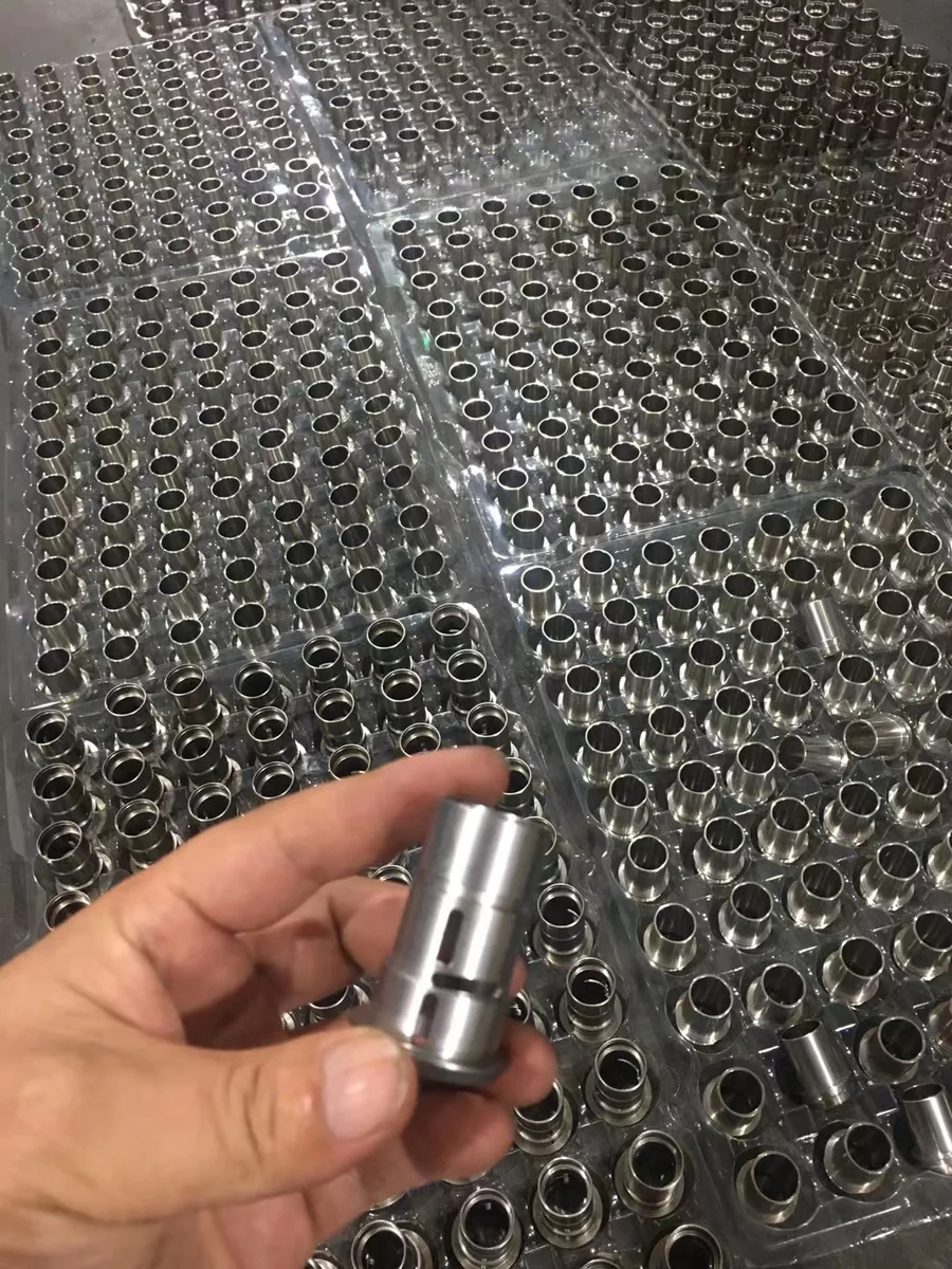
CNC Machining
CNC Machining

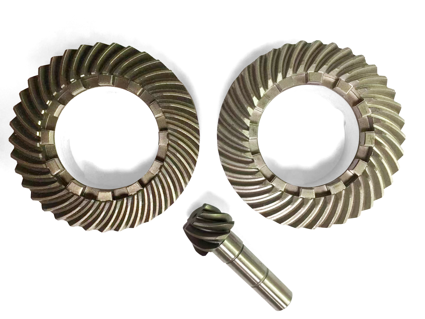
Printed near-net geometry can be CNC machined where precision surfaces or features exceed practical as-printed capability. Typical applications include: Best suited for: Precision holes · Threads · Datums · Sealing faces · Bearing locations · Flat mounting surfaces · Critical interfaces

Precision holes · Threads · Datums · Sealing faces · Bearing locations · Flat mounting surfaces · Critical interfaces

Mockup additive manufacturing / engineer reviewed

Heat Treatment and HIP

Metal additive components may require stress relief, heat treatment or HIP depending on alloy, application and required material condition. These operations are defined as part of the metal additive process route.

Mockup additive manufacturing / engineer reviewed

Inspection room for dimensional verification
08 / 3D PRINTING

Quality Control for 3D Printed Parts

Inspection should reflect both process capability and the purpose of the component. A visual concept model and a functional production component should not receive the same control plan. Depending on the project, quality records and verification may include:

  • Key requirements
09 / 3D PRINTING

Design for Additive Manufacturing

Designing a part for additive manufacturing involves more than exporting an STL file. Process-aware design can reduce failures, improve surfaces and lower downstream finishing costs.

01

1. Design Wall Thickness for the Process

Very thin walls can distort, break or print inconsistently. Required thickness depends on material, wall height, unsupported span, orientation and functional load. Use process-specific guidance rather than applying one minimum wall value to every technology.

02

2. Orient Critical Surfaces Intentionally

Orientation influences surface condition, supports, dimensional behavior and mechanical properties. Identify the most important functional and cosmetic surfaces before the build is prepared.

03

3. Consider Direction-Dependent Properties

Layer-based manufacturing can create anisotropic mechanical behavior. The expected load direction should therefore be considered when selecting both process and orientation.

04

4. Provide Escape and Drain Paths

Hollow SLA components can trap uncured resin. SLS and MJF parts can trap powder. Metal additive components can also retain trapped powder in internal passages. Provide practical escape, drain and cleaning paths when designing enclosed geometry.

05

5. Define Mating Clearances

Printed parts require realistic clearances for assemblies, moving interfaces and nested components. The required clearance depends on: Do not assume CAD zero-clearance assemblies will function correctly after printing. Best suited for: Printing process · Material · Part size · Orientation · Surface condition · Required movement · Post-processing

06

6. Plan Critical Interfaces Separately

Not every feature needs to be produced to final condition during printing. Critical interfaces can often be designed with additional stock and finished later. Examples include: This approach allows additive manufacturing to create the complex near-net geometry while machining controls the features that require greater precision. Best suited for: Bearing bores · Precision holes · Threaded interfaces · Sealing surfaces · Datum faces · Locating features · Mounting surfaces

07

7. Avoid Inaccessible Internal Features

An internal cavity may be printable while still being impossible to clean or inspect. Before approving enclosed geometry, consider: Manufacturability includes cleaning and verification—not only successful printing. Best suited for: How support material will be removed · How resin or powder will escape · Whether the feature can be visually inspected · Whether CT or another verification method is practical · Whether internal surface condition matters · Whether trapped material could affect function

08

8. Design Around Post-Processing

Finishing operations need physical access. If a surface must be sanded, polished, drilled, threaded or machined, its position and surrounding geometry should allow the required tool or finishing method to reach it. This is especially important when combining additive manufacturing with CNC machining.

10 / 3D PRINTING

3D Printing Project Examples

The following examples show how process selection changes according to what the part needs to prove.

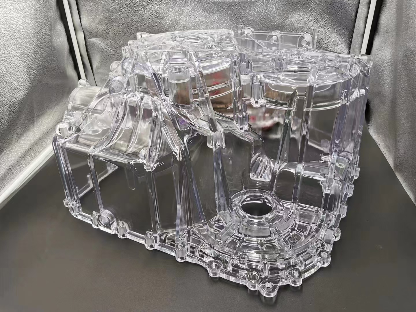
SLA Transparent Flow Prototype
01

SLA Transparent Flow Prototype

Application: Transparent fluid-handling prototype Process: SLA Material: Clear photopolymer resin selected for prototype requirements Quantity: Low-volume engineering prototypes Requirement: Visualize internal flow paths and confirm external assembly geometry Post-process: Support removal, sanding, polishing and clear finishing Evidence: Dimensional inspection of critical interfaces and visual review of internal geometry Result: The engineering team received a transparent physical model for fit and flow evaluation without producing dedicated tooling. The value of SLA in this case was not simply low-volume production. The clear prototype allowed internal geometry to be evaluated physically before committing to a more expensive production route.

SLA Cosmetic Housing Prototype
02

SLA Cosmetic Housing Prototype

Application: Consumer or industrial equipment housing Process: SLA Material: ABS-like prototype resin Quantity: Prototype quantity Requirement: Validate shape, button positions, gaps and overall appearance before tooling Post-process: Sanding, primer and cosmetic painting Evidence: Visual standard plus dimensional checks around assembly interfaces Result: A presentation-quality prototype supported design approval while the CAD model remained easy to revise. The ABS-like material was selected for prototype behavior and surface quality. It was not represented as equivalent to molded production ABS.

SLS Functional Nylon Assembly
03

SLS Functional Nylon Assembly

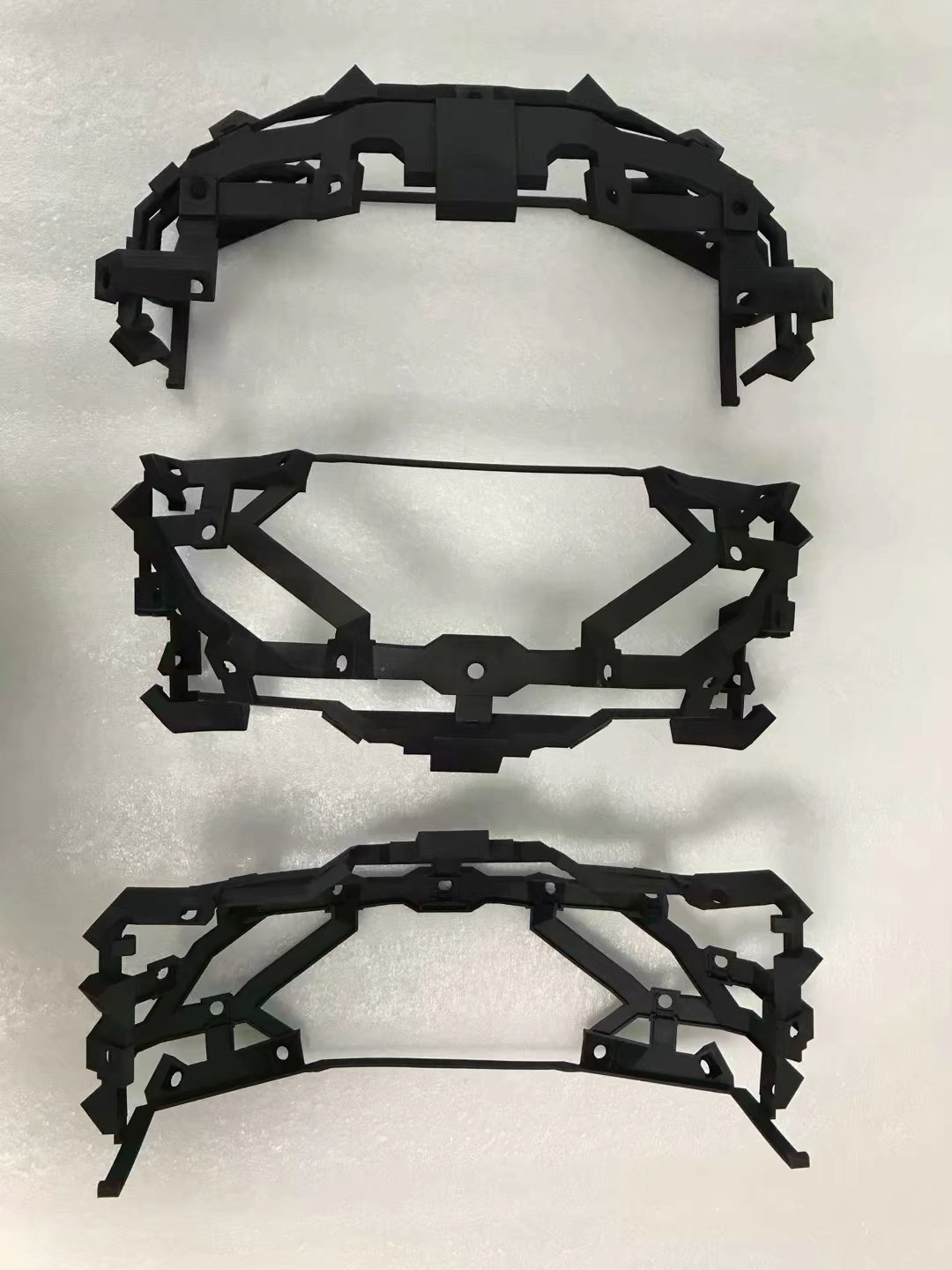
Application: Mechanical enclosure and internal mounting components Process: SLS Material: PA12 Quantity: Engineering validation batch Requirement: Check assembly, snap features, cable routing and installation geometry Post-process: Powder removal, blasting and selected dyeing Evidence: Dimensional sampling of mounting points and physical assembly testing Result: Multiple functional parts were manufactured without dedicated supports or injection-molding tooling. SLS was appropriate because the project required complex nylon geometry and functional assembly rather than premium cosmetic surfaces.

MJF Low-Volume Production Components
04

MJF Low-Volume Production Components

Application: Customized equipment brackets and covers Process: MJF Material: PA12 Quantity: Small production batch Requirement: Produce repeatable functional components while avoiding tooling investment Post-process: Cleaning, blasting and dyeing Evidence: Dimensional sampling and visual acceptance criteria Result: Multiple components were nested within production builds and supplied as a low-volume manufacturing route. This approach can be useful where demand does not yet justify tooling or where several product variants must remain available simultaneously.

FDM Manufacturing Fixture
05

FDM Manufacturing Fixture

Application: Assembly fixture Process: FDM Material: Engineering thermoplastic selected for load and environment Quantity: One-off and replacement fixtures Requirement: Hold components consistently during a manual assembly operation Post-process: Insert installation and local machining where required Evidence: Fit check and dimensional verification of locating points Result: The fixture was produced without conventional tooling and could be revised directly from the digital model. For this application, manufacturing speed and functional geometry were more important than cosmetic surface quality.

Metal Additive Internal-Flow Component
06

Metal Additive Internal-Flow Component

Application: Compact fluid manifold Process: Metal laser powder-bed fusion Material: Metal alloy selected according to operating conditions Quantity: Low-volume high-value components Requirement: Integrate complex internal channels that would be difficult to drill and assemble conventionally Post-process: Stress relief, support removal and CNC machining of ports and sealing surfaces Evidence: Dimensional inspection plus project-specific internal-flow or leak verification Result: Additive manufacturing created the internal geometry while CNC machining controlled the precision interfaces. This hybrid route demonstrates why metal additive manufacturing and conventional machining should often be considered together rather than as competing technologies. Project examples represent typical manufacturing scenarios. Final material, process, tolerance, qualification and inspection requirements are confirmed for each project.

COMMON QUESTIONS

Frequently Asked Questions About 3D Printing Services

Which 3D printing process should I choose?+

The correct process depends on what the part needs to achieve. SLA is often preferred for fine detail and appearance. SLS and MJF are strong options for functional nylon parts. FDM can be economical for larger prototypes, fixtures and concept models. Metal additive manufacturing is appropriate when complex metal geometry creates enough value to justify the process. Part size, quantity, material properties, surface requirements, dimensional requirements and post-processing can change the recommendation. Upload the model and application information so Mockup can compare the available routes.

What is the difference between SLA, SLS and MJF?+

SLA cures liquid photopolymer resin and is commonly selected for detailed or cosmetic prototypes. SLS fuses polymer powder and produces functional nylon components without conventional support structures. MJF also uses a powder-bed process and is commonly selected for repeatable functional nylon components and efficient small-batch production. The most suitable process depends on the balance between appearance, mechanical behavior, quantity, geometry and cost.

Can 3D printing produce end-use parts?+

Yes, for suitable applications. SLS, MJF, FDM and metal additive technologies can all be used for end-use components when material properties, process control, orientation, finishing and inspection match the service conditions. The fact that a material is printable does not automatically make it appropriate for a production application. Environmental exposure, load, temperature, chemicals, fatigue, UV, moisture and regulatory requirements should be considered before approval.

Is 3D printing suitable for low-volume production?+

Yes. One of the main advantages of additive manufacturing is the ability to produce parts without dedicated molds or hard tooling. This can make 3D printing attractive for: As quantities increase, Mockup can also compare additive manufacturing against CNC machining, vacuum casting, injection molding and other production routes.

  • Pilot production
  • Bridge production
  • Customized components
  • Spare parts
  • Multiple product variants
  • Low-volume functional parts
  • Demand validation before tooling
How accurate is 3D printing?+

There is no single accuracy value that applies to all 3D printing technologies. Accuracy depends on: Critical dimensions should be identified on an engineering drawing. Mockup can then determine whether those requirements are practical in the as-printed condition or whether secondary machining is recommended.

  • Process
  • Material
  • Part dimensions
  • Geometry
  • Build orientation
  • Wall thickness
  • Feature position
  • Post-processing
Can you make tight-tolerance 3D printed parts?+

Certain features can be controlled more closely than others, but tight functional interfaces should be reviewed individually. When required, a part can be printed near net shape and then CNC machined at selected surfaces, bores, holes or datums. This is particularly common for metal additive components.

Can you 3D print clear parts?+

Yes. SLA can produce clear or translucent prototype components using suitable photopolymer resins. However, transparency depends heavily on geometry and post-processing. Support removal, sanding, polishing and clear coating may be necessary when optical appearance is important. A clear SLA prototype should not automatically be assumed to provide the same optical, thermal or mechanical behavior as molded transparent thermoplastics.

Can you print flexible parts?+

Yes, depending on the required flexibility and application. TPU and selected flexible photopolymer systems may be available for flexible prototypes and functional parts. Provide the expected hardness, deformation, load and environment so the material can be selected appropriately.

Can 3D printed parts be painted?+

Yes. Many printed components can be sanded, primed and painted. SLA is particularly suitable for presentation models that require a high-quality cosmetic finish. The final appearance depends on surface preparation, part geometry and the required visual standard.

Can SLS and MJF parts be dyed?+

Yes, compatible nylon components can often be dyed after printing. Dyeing can provide a more consistent appearance than the natural printed surface. Color requirements should be specified during quotation, particularly when multiple production batches need to match.

Do 3D printed parts need support structures?+

It depends on the technology. SLA usually requires supports. FDM often requires supports for overhangs or complex geometry. Metal powder-bed fusion normally requires supports for selected surfaces and thermal control. SLS and MJF generally do not require conventional support structures because surrounding powder supports the part during printing.

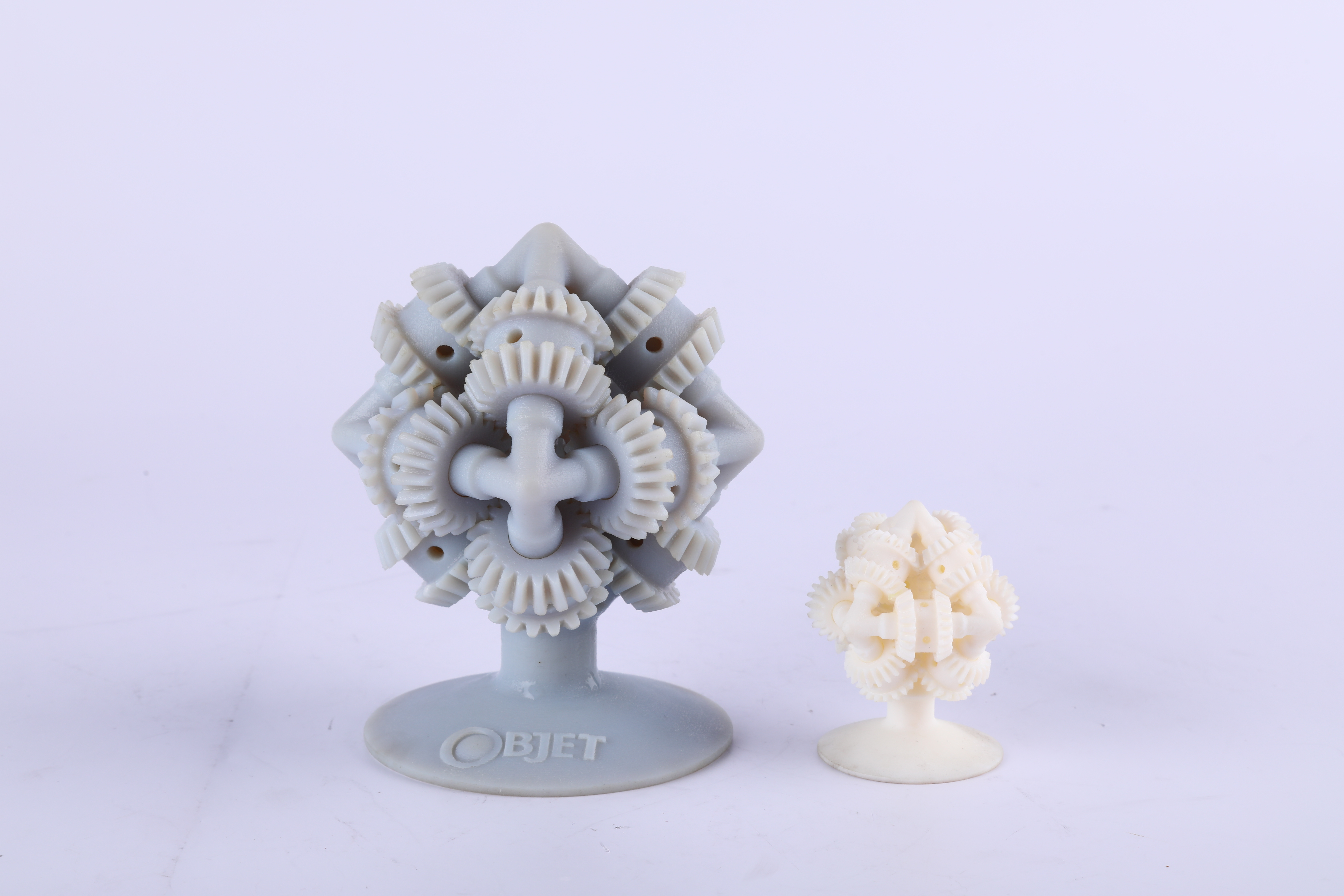
Can you print assemblies as one part?+

Some additive technologies can create moving or nested geometries that would be difficult to manufacture conventionally. However, clearances, trapped powder or resin, support removal, cleaning and inspection must all be considered. Printing an assembly as one piece is only useful when the resulting component can be cleaned, verified and used reliably.

Can you add threads to 3D printed parts?+

Yes. Depending on material, size and required durability, threads may be: For frequently assembled polymer parts, threaded inserts can provide a more durable interface than small printed threads.

  • Printed directly
  • Tapped after printing
  • CNC machined
  • Created with threaded inserts
Can 3D printed parts be CNC machined afterward?+

Yes. CNC post-machining is useful when additive manufacturing creates the overall geometry but specific interfaces need improved tolerance or surface finish. Typical post-machined features include bores, holes, threads, datums, sealing faces and mounting surfaces.

Can you inspect internal channels?+

Depending on geometry and project requirements, internal features may be evaluated using methods such as visual inspection, flow testing, pressure testing, leak testing or CT. Inspection requirements should be identified during design because some internal geometries are difficult to verify after printing.

What materials are available for 3D printing?+

Material families may include: Exact materials are confirmed according to selected technology and project requirements.

  • Photopolymer resins
  • PA11
  • PA12
  • Filled nylons
  • TPU
  • Engineering FDM thermoplastics
  • Aluminum alloys
  • Stainless steels
  • Titanium alloys
  • Nickel-based alloys
  • Tool and maraging steels
Is an ABS-like resin the same as ABS?+

No. “ABS-like” generally describes a photopolymer resin engineered to provide some characteristics associated with ABS. It is not chemically or mechanically identical to injection-molded ABS. If actual production-material behavior is important, the material should be selected using relevant technical property data.

What file formats should I provide?+

STEP or STP is preferred when dimensional accuracy and engineering review are important. STL or 3MF files may also be accepted for suitable projects. For functional parts, include an engineering drawing identifying: A mesh file alone may not communicate all manufacturing requirements.

  • Critical dimensions
  • Tolerances
  • Threads
  • Surface requirements
  • Material requirements
  • Finish requirements
  • Inspection requirements
Can Mockup help if I do not know which process to use?+

Yes. You do not need to decide between SLA, SLS, MJF, FDM or another manufacturing process before requesting a quote. Send the CAD model, quantity and application. Mockup can review what the part needs to prove and recommend an appropriate process, material and post-processing route.

Can you compare 3D printing with CNC machining or injection molding?+

Yes. 3D printing is not always the best manufacturing solution. CNC machining may be more appropriate for tight-tolerance components in production materials. Injection molding may provide better economics at sustained production volumes. Vacuum casting may be useful when a small batch of molded-like prototypes is required. Mockup evaluates the project around geometry, quantity, material, tolerance, lead time and lifecycle rather than forcing every inquiry into an additive process.

ENGINEERING REVIEW

Get a 3D Printing Quote and Process Review

Upload your 3D model and tell us what the part needs to do. Mockup will review the geometry, quantity, material requirements, critical dimensions, surface expectations and application before recommending SLA, SLS, MJF, FDM, metal additive manufacturing or another suitable manufacturing route. From early concept models to functional prototypes and low-volume production, the goal is the same: choose a process that supports the next engineering or commercial decision—not simply produce a printable shape. Upload my 3D model ↗ Encrypted upload · Confidential handling · Engineer review

Upload my 3D model ↗
START A PROJECTUpload my 3D model