
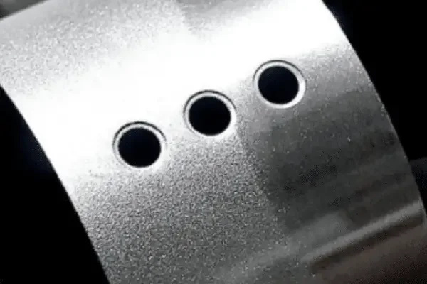
Select and specify CNC part finishes by function, substrate, dimensional consequence and acceptance method—not color alone. This guide compares machined texture, mechanical preparation, conversion treatments, plating and organic coatings, then shows what belongs on the drawing and RFQ.
Choose the finish from the job the surface must do.
A useful finish specification begins with the required outcome: corrosion protection, wear resistance, controlled friction, electrical continuity or isolation, cleanability, reflectivity, color, texture or simply removal of machining marks. The substrate and geometry then narrow the process choices. The drawing closes the loop by defining preparation, masked features, coating thickness where relevant and how the finished part will be accepted.
Surface texture and surface treatment are related but different. A roughness callout describes measured texture on a defined surface. Anodizing, plating, passivation or paint describes a post-machining process. A part can meet one requirement and fail the other, so critical projects should specify both independently.
There is no universally best finish. As-machined may be the most controlled option for a precision fit; bead blast plus anodize may suit a cosmetic aluminum housing; passivation may suit a stainless component where cleanliness and corrosion performance matter; and powder coating may suit a steel enclosure that needs a durable colored barrier.
- 01Start with functional exposure and mating conditions
- 01Confirm that the finish is compatible with the exact alloy and temper
- 01Plan dimensional allowance, masking and inspection before machining
- 01Use an approved sample when appearance is a controlled requirement
Do not use “surface finish” to mean three different things.
Engineering teams often use the same phrase for machined roughness, visual texture and a chemical or deposited coating. Separating them prevents ambiguous drawings and incorrect supplier assumptions.
| Requirement | What it controls | Typical communication | Common failure |
|---|---|---|---|
| Surface roughness | Microscopic texture affecting sealing, friction, fatigue or appearance | Ra, Rz or another parameter plus standard, cutoff and direction where needed | A visual sample is treated as a roughness specification |
| Mechanical appearance | Directional or non-directional texture created by blasting, brushing, tumbling or polishing | Process, media or pattern, cosmetic zones and approved sample | Texture varies around edges, holes or inaccessible areas |
| Surface treatment | Corrosion, wear, conductivity, color or barrier behavior | Process specification, class/type, thickness, color and masking | Finish name is given without substrate or acceptance criteria |
Compare finish families before selecting a process name.
The table below is a screening tool, not a substitute for the governing process specification. Exact thickness, color range, corrosion performance, edge response and material compatibility must be confirmed for the selected alloy, geometry and service environment.
| Finish family | Common substrates | Primary reasons to choose it | Design and control concerns |
|---|---|---|---|
| As machined / finish machined | Machinable metals and rigid plastics | Fastest route; controlled functional faces; no added coating | Tool marks, burr control, lay direction and local roughness |
| Bead blast / abrasive blast | Aluminum, stainless and other suitable metals | Uniform matte appearance; preparation before coating | Media, edge rounding, embedded contamination, masking and lot variation |
| Brushed / polished | Stainless, aluminum, brass and suitable metals | Directional cosmetic texture or reduced visual roughness | Grain direction, geometry access, material removal and sample approval |
| Type II anodize | Suitable aluminum alloys | Corrosion protection, color and electrical insulation | Alloy-dependent color, oxide growth, rack marks, masking and sealing |
| Type III hard anodize | Suitable aluminum alloys | Harder wear-oriented oxide layer | Greater dimensional consequence, color limits, sharp edges and fits |
| Chemical conversion coating | Suitable aluminum alloys | Corrosion protection, paint preparation or controlled conductivity by specification | Contact areas, coating class, cosmetic variation and handling |
| Passivation | Stainless steels | Removal of free-iron contamination and support of the passive surface | Correct stainless grade, cleanliness, governing specification and verification |
| Electroplating / electroless plating | Process-compatible metals | Wear, corrosion, appearance, solderability or conductivity | Thickness distribution, hydrogen risk where applicable, internal features and final size |
| Powder coat / wet paint | Metals with compatible pretreatment | Durable colored barrier and broad cosmetic options | Film build, threads, holes, grounding points, edges and cure temperature |
Treat alloy, preparation and anodize as one system.
Aluminum finish appearance is influenced by alloying elements, temper, stock route, machining marks and surface preparation. Two parts called “black anodized” can differ visibly if the alloy, blast condition, rack position or lot changes. Cosmetic consistency therefore starts before the anodizing bath.
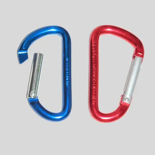
Type II anodizing is commonly selected for corrosion protection and decorative color on compatible aluminum alloys. Type III hard anodizing is selected when a thicker, harder oxide is needed for wear-oriented surfaces. Neither label is complete without the governing specification, class or color, sealing requirement, thickness where applicable and masked features.
Bead blasting before anodizing can reduce the visibility of machining marks and create a more uniform matte texture, but it also changes edge definition and can make surface preparation a controlling variable. A signed limit sample is valuable when color and texture matter to the product.
- 04Keep appearance-critical parts in a controlled alloy and lot where practical
- 04Identify rack-contact locations and cosmetic exclusion zones
- 04Mask bearing seats, threads, contacts or sealing features when required
- 04State whether final dimensions apply after anodizing
Corrosion protection depends on the material and environment.
Passivation is not paint and does not hide machining marks. It is used on suitable stainless steels to remove free-iron contamination and support the alloy’s passive condition under a defined process. Carbon and low-alloy steels generally need a different barrier or conversion system when corrosion protection is required.
Plating can provide corrosion, wear, appearance or electrical properties, but deposit distribution may vary across edges, recesses and internal features. The drawing should identify the required process, thickness range and inspection locations rather than assuming one nominal value applies uniformly everywhere.
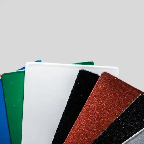
Powder coating and wet paint can provide a durable colored barrier for steel fabrications and housings. Pretreatment, edge coverage, cure temperature, film build and damage repair all affect real performance. Threads, grounding areas, identification marks and mating faces usually need explicit review.
- 05Specify the environment rather than asking only for “corrosion resistant”
- 05Do not substitute passivation for a stainless-grade requirement
- 05Review plating on high-strength steel for process-specific risk
- 05Define coating repair and acceptance for welded or handled assemblies
Put finishing inside the tolerance plan—not after it.
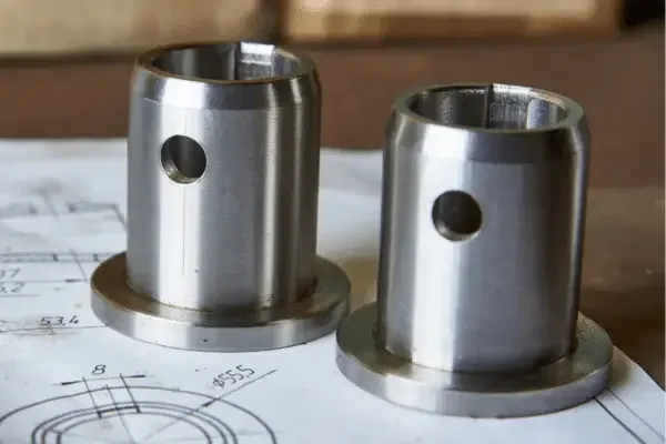
A finish may add material, convert part of the substrate, remove peaks during preparation or round an edge. These effects matter most at bores, shafts, threads, sealing lands, bearing seats, electrical contacts and precision mating faces. If the machining drawing ignores finishing, a correct pre-finish part can become a nonconforming final part.
A coating thickness applied per surface changes a diameter on both sides. Internal and external features may not receive identical buildup, and current density or line-of-sight can make some deposited processes less uniform around edges and recesses. For this reason, the finish specification and measurement locations must be agreed together.
The drawing should state whether a dimension is controlled before finish, after finish or through a post-finish operation such as grinding, honing, reaming or thread chasing. Masking is not automatically the best answer: it can introduce transition lines and handling complexity, so allowance and selective final machining should also be evaluated.
| Feature | Potential finish effect | Typical control decision |
|---|---|---|
| Precision bore or shaft | Buildup changes clearance or interference | Allowance, masking or final machining |
| Thread | Pitch diameter changes; coating may bridge or chip | Mask, plug, chase or specify coated-thread acceptance |
| Grounding/contact area | Insulating oxide or paint interrupts continuity | Mask and identify contact footprint |
| Sealing face | Texture or coating affects compression and leakage | Control roughness and final-condition inspection |
| Sharp edge | Reduced coating coverage or edge rounding | Define edge break and coating acceptance |
| Datum/inspection surface | Preparation changes the reference condition | Protect or inspect in the final state |
Replace subjective adjectives with zones, samples and conditions.
“Smooth,” “matte,” “satin,” “no marks” and “color match” are not measurable acceptance criteria by themselves. Cosmetic requirements become repeatable when the drawing identifies the visible zones, surface-preparation route, color reference, viewing distance, lighting, orientation and permitted defect limits.
Classify surfaces by importance. A primary customer-facing face may need tighter control than a hidden interior, rack contact or assembly interface. Mark those zones on the model or drawing so finishing, fixturing, packaging and inspection share the same requirement.
For color anodize, paint, powder coat or brushed metal, an approved physical sample is often the clearest master. Instrumental color or gloss limits can be added when the product needs objective lot-to-lot control, but the method and measurement geometry must be agreed.
- 07Define primary, secondary and non-cosmetic surfaces
- 07Locate permitted rack, hook or electrical-contact marks
- 07Agree sample ownership, revision and storage
- 07Specify protective packaging for appearance-critical delivery
The finish route can dominate the second half of the order.
Finishing adds transport or internal queue time, preparation, masking, racking, inspection, rework risk and sometimes minimum batch economics. A complex masking plan or tight color match can cost more than the nominal coating itself. The lowest-risk specification controls only what the product needs.
Cost usually rises with multiple cosmetic zones, special colors, individually plugged holes, selective thickness, polished surfaces, certificates, coupon testing and very small batches. Combining similar parts under one controlled finish route can help, but only when alloys, pretreatments and acceptance requirements are compatible.
Quality evidence should be selected during quotation. Depending on the project, this can include visual inspection, roughness results, coating-thickness readings, color or gloss checks, adhesion or corrosion-test records, process certificates and final dimensional reports. These records are not automatic for every order.
- 08Separate functional requirements from optional appearance preferences
- 08Minimize masked features through design where practical
- 08Confirm sample and test requirements before purchase order release
- 08Plan final dimensional inspection after the complete process chain
A complete finish callout answers nine questions.
Send the 3D model for geometry and a controlled drawing for surface requirements. The finish note should be specific enough to quote, manufacture and inspect without relying on verbal history.
- 09What exact substrate, grade, temper or material condition is being finished?
- 09Which process specification, type, class or finish system applies?
- 09What functional outcome and service environment must it support?
- 09Which surfaces are cosmetic, functional, masked or excluded?
- 09What thickness, roughness, color, gloss or texture limits apply—and where?
- 09Do dimensions apply before finish, after finish or after a final machining step?
- 09Where may rack, hook, plug, contact or witness marks appear?
- 09What sample, test method, certificate or inspection report is required?
- 09How must finished parts be handled, separated, packaged and labeled?
Review machining, finishing and inspection as one route.
Mockup’s engineering review connects the material, machining allowance, surface preparation, finishing method, masking plan and final inspection condition before production release. Anodizing, sandblasting, electroplating, coating, brushing, passivation, screen printing, laser marking and etched nameplates are listed within the current operating scope; other treatments and project-specific requirements are confirmed during review.
The drawing controls. If a finish or tolerance requirement is incomplete, engineering identifies the missing decision rather than applying a universal default. Complete straightforward sample or routine aluminum RFQs are normally quoted within 12 hours; complex multi-axis, precision-tolerance, multi-process or new-material RFQs are normally quoted within 24 hours after the required information is complete.
Send a STEP or Parasolid model, PDF drawing, exact material, quantities, finish callout, cosmetic zones and required records. Mutual general or project-specific NDAs can be signed before core confidential 3D files are transferred.
Guidance connected to real manufacturing decisions.
Mockup helps product teams move from CAD review and DFM through manufacturing, inspection and repeat production. Our engineering guides translate that operating experience into practical decisions you can apply before requesting a quote.
Questions from engineering teams.
What is the difference between surface roughness and surface finish?+
Surface roughness is a measured component of surface texture, commonly expressed with parameters such as Ra or Rz under a defined method. Surface finish is often used more broadly for visual texture or a post-process such as anodizing, plating or paint. Critical drawings should specify these requirements separately.
Does anodizing change CNC part dimensions?+
Yes. Anodizing converts the aluminum surface and creates an oxide layer with a dimensional consequence. Fits, bores, threads and mating features may need allowance, masking or final-condition inspection based on the specified anodize process.
Is bead blasting the same as anodizing?+
No. Bead blasting is a mechanical surface-preparation process that creates texture. Anodizing is an electrochemical conversion treatment for suitable aluminum alloys. They are often combined, but each needs its own requirement.
Should threads and precision bores be masked before coating?+
Sometimes, but not automatically. The decision depends on finish type, thickness, corrosion exposure, fit and final inspection. Masking, machining allowance and post-finish machining should be compared during DFM.
How do I specify a cosmetic finish?+
Identify cosmetic zones, process and preparation, color or texture reference, acceptable variation, rack-mark locations, viewing conditions and packaging. For appearance-critical parts, approve and control a representative physical sample.
Which finish is best for aluminum CNC parts?+
There is no universal best option. As-machined, bead blasted, Type II anodized, Type III hard anodized, chemical conversion coated, plated, painted or powder-coated surfaces solve different functional and visual requirements. Select from the alloy, environment, wear, conductivity, fit and appearance needs.
What information is needed for a surface-finishing quote?+
Send the 3D model, controlled drawing, exact material, quantity, finish specification, color or texture, masked and cosmetic zones, final dimensional requirements, required tests or certificates and packaging expectations.