
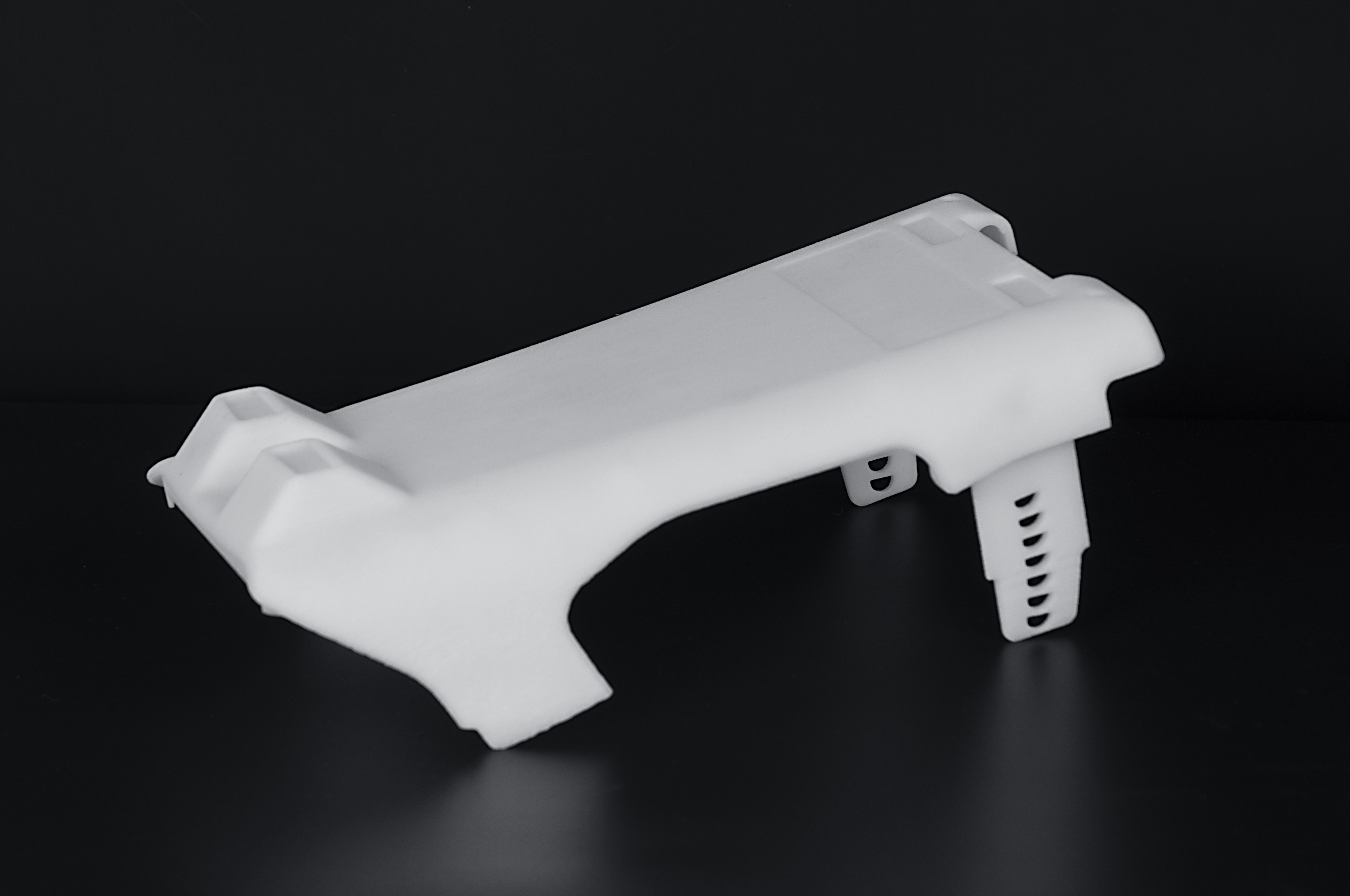
FUNCTION + GEOMETRY
SLS
Functional nylon, complex support-free geometry, ducts, snap fits and low-volume batches.
Produce durable nylon prototypes, complex assemblies and low-volume functional parts without dedicated support structures.
Encrypted upload · Confidential handling · Engineer review
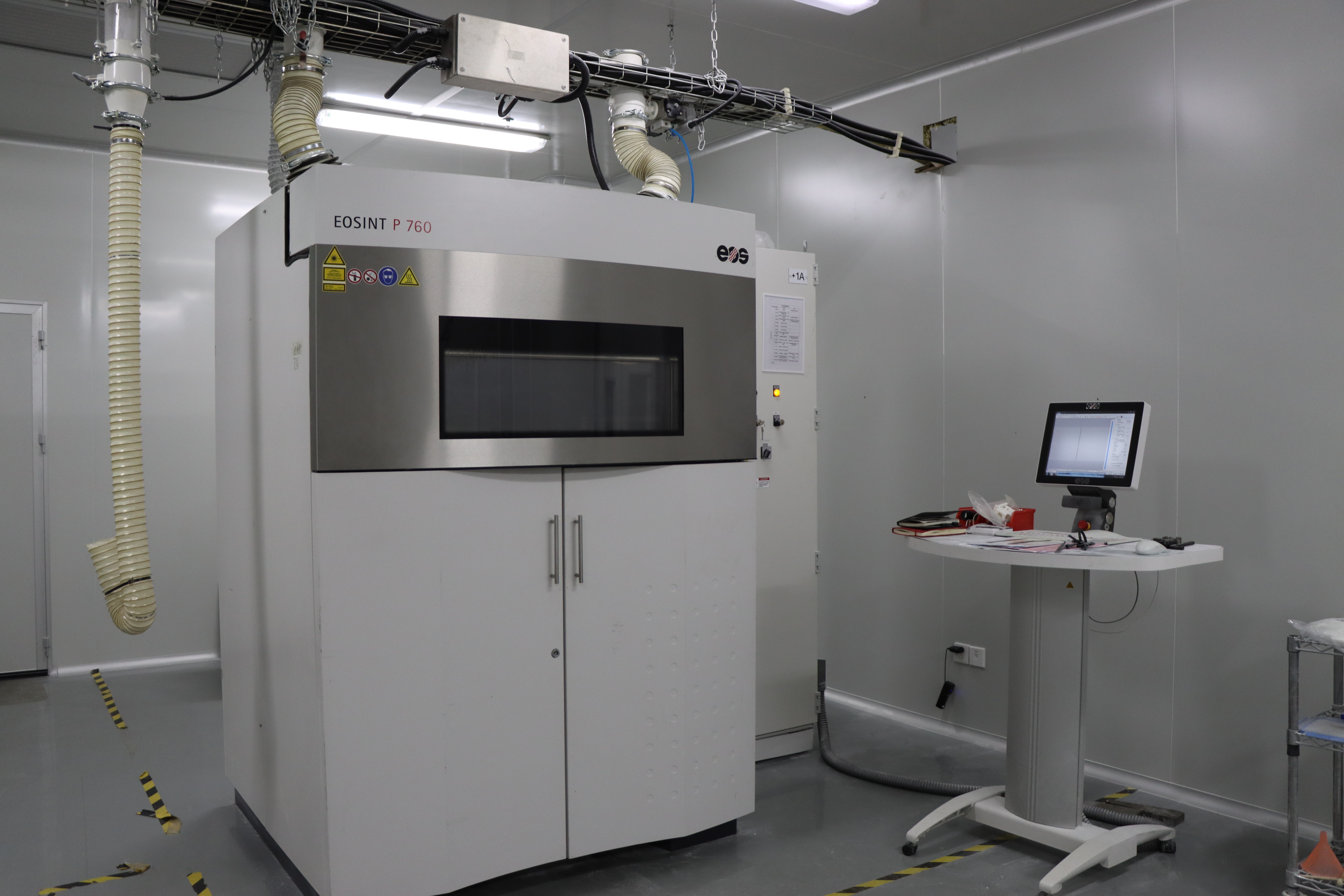
Choose SLS when functional nylon behavior and support-free geometric freedom matter more than a presentation-smooth surface. The powder bed supports complex geometry, while powder removal, thermal behavior and final surface requirements remain part of the engineering review.
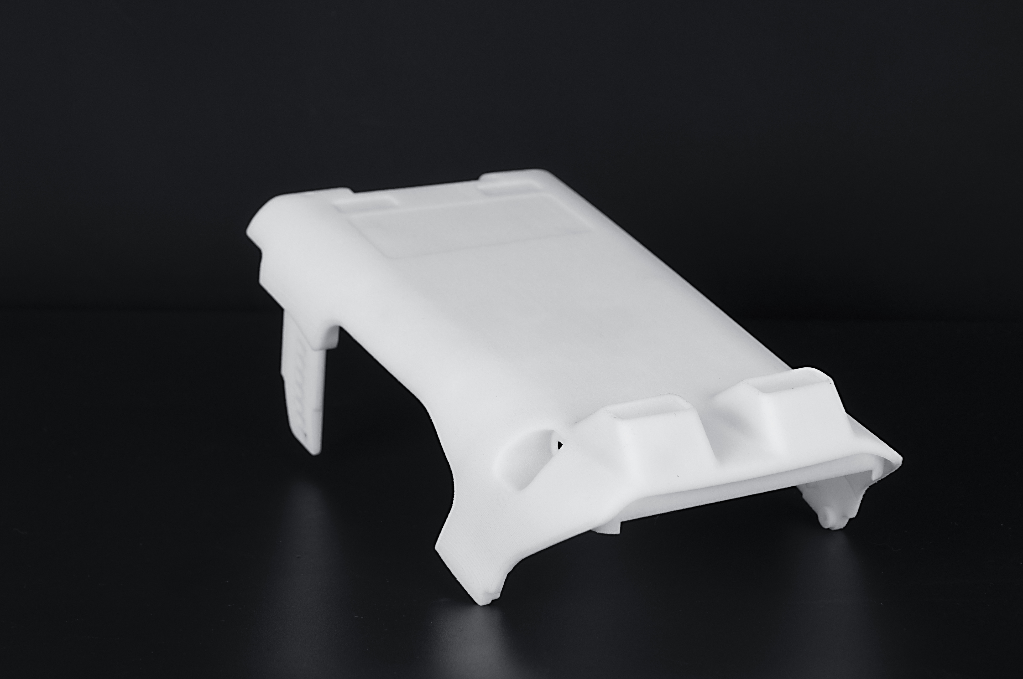
Mockup compares geometry, surface, material behavior, quantity and critical dimensions before recommending a process.
Functional nylon, complex support-free geometry, ducts, snap fits and low-volume batches.
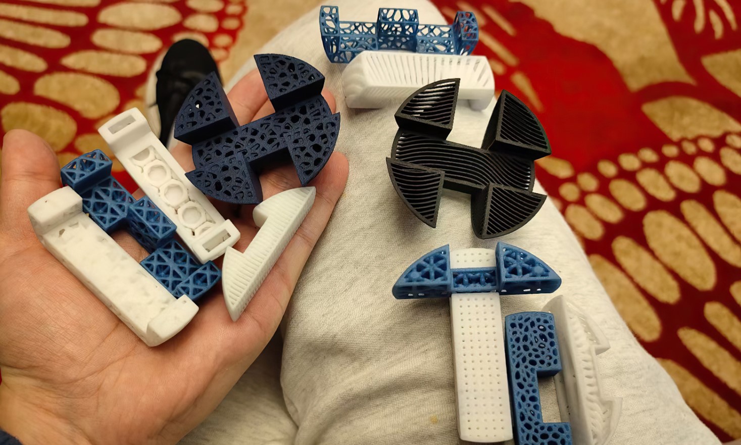
Fine visual detail, smooth presentation surfaces, clear parts and master patterns.
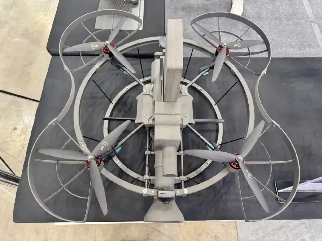
Alternative routes when batch economics, large size, tight machining or sustained production dominate.
A controlled route continues well beyond the powder-bed build.
Review walls, channels, clearances, load direction, powder escape and critical dimensions.
Plan build position, identification, density and revision control.
A laser fuses polymer powder layer by layer while surrounding powder supports the geometry.
Cool the build before excavation to manage thermal and dimensional risk.
Remove loose powder from surfaces, holes, pockets, channels and moving interfaces.
Complete dyeing, smoothing, machining, inserts, assembly and agreed verification.
A material-family name alone does not define final performance. Review load, impact, temperature, chemicals, moisture, repeated assembly and expected service life before confirming the grade and build route.
Machine, material, size, geometry, orientation and finishing determine practical capability.
Finishing can change appearance, sealing behavior, edge definition and dimensions. Protect critical interfaces in the process plan.
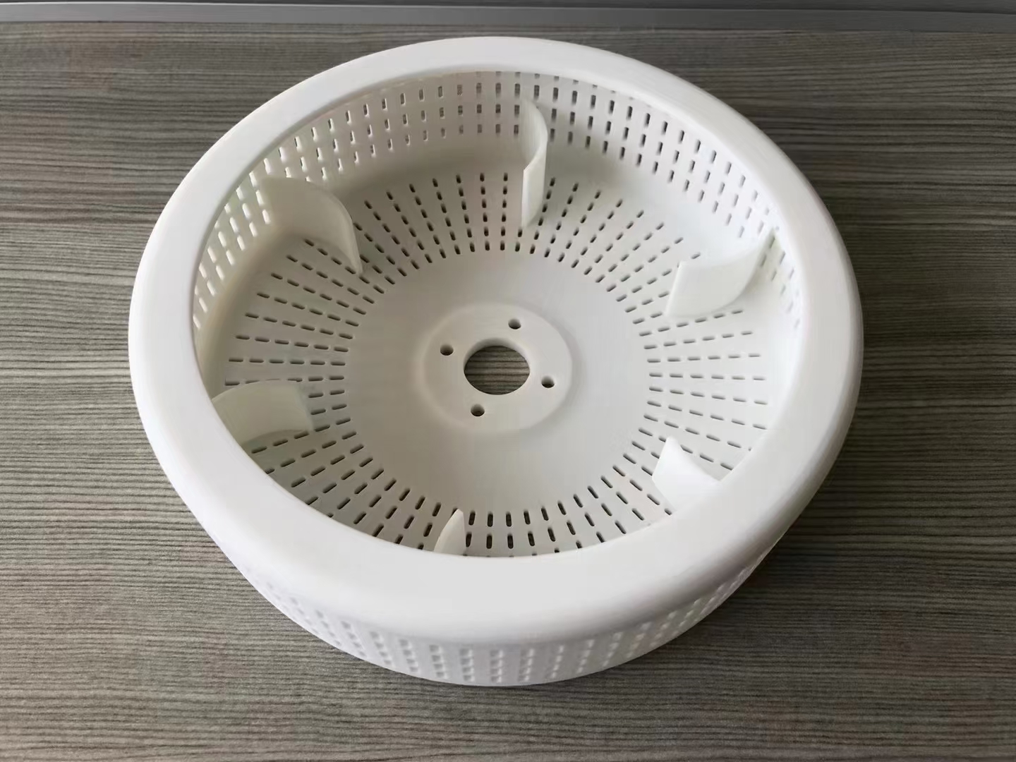
Remove loose powder from surfaces, holes, pockets and channels, then create a more uniform matte appearance.
Create black or specified-color parts with batch expectations and coating thickness defined.
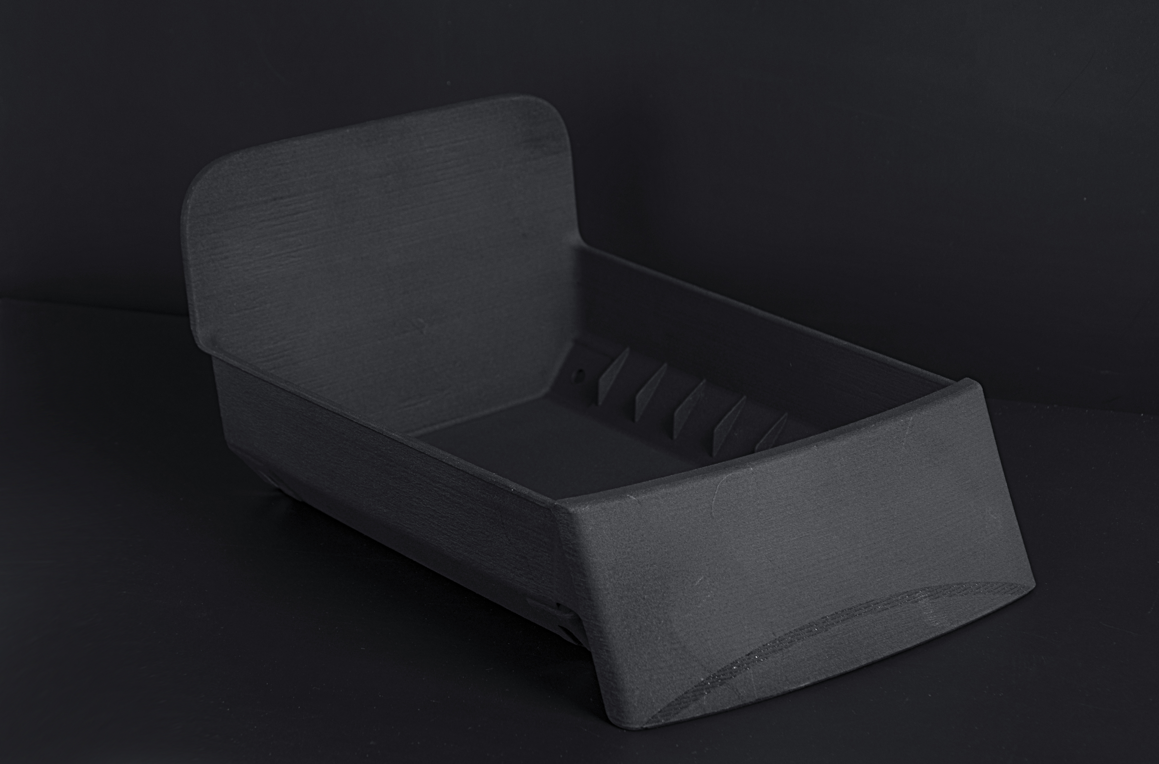
Reduce roughness or improve leak behavior using a route reviewed against geometry and acceptance criteria.
Finish precision holes, datums, sealing faces and reusable fastening points.
Support-free does not mean design-free. Powder removal, thermal behavior, motion and finishing still require deliberate DFM.
Use gradual transitions and review large solid masses.
Make openings practical for the cavity volume and cleaning route.
Avoid inaccessible blind passages without a confirmed strategy.
Never use CAD zero clearance for intended motion.
Consider deflection, root radius, cycles and build orientation.
Add durable part, revision and variant markings.
State fluid, pressure, temperature, duration and allowable leakage.
Provide impact, fatigue, chemicals, moisture, UV and service life.
Define fits and inspection in the final delivered condition.
A development duct, production fixture and customer-facing low-volume component require different evidence. Mockup matches dimensional, material, finish and functional inspection to the drawing, project risk and intended end use.
A development duct, production fixture and customer-facing low-volume component require different evidence. Mockup matches dimensional, material, finish and functional inspection to the drawing, project risk and intended end use.
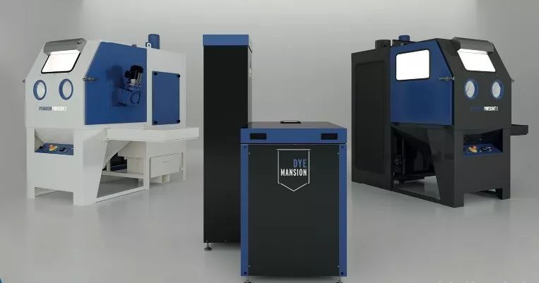
Final material, tolerance, finish and inspection requirements are confirmed for each project.
PA12 engineering batch with bead blasting, dyeing and mating-surface assembly checks.
Single-piece curved airflow path designed with accessible powder-removal openings.
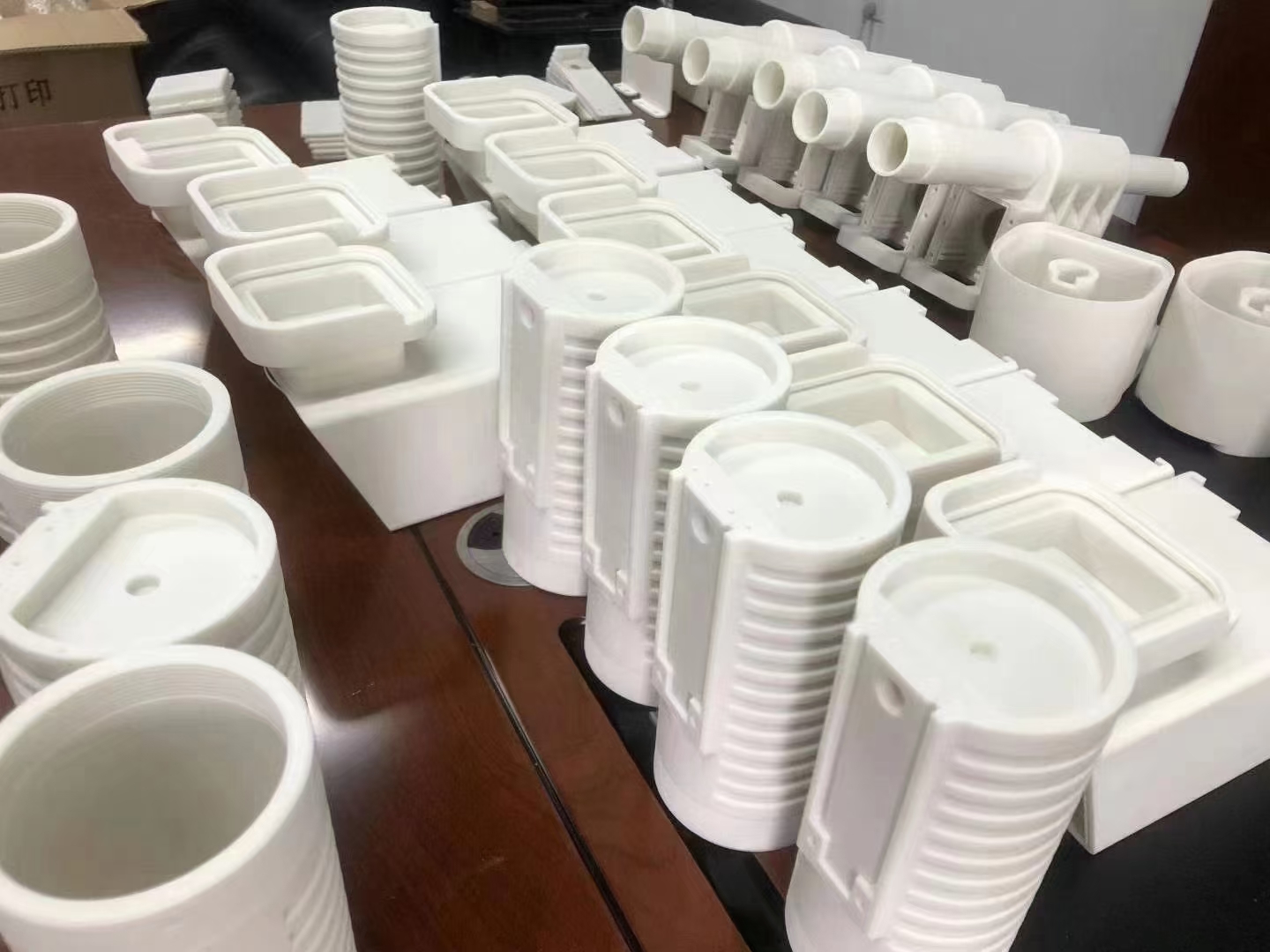
Brackets, sensor mounts, cable guides and covers sharing production builds across variants.
Functional PA12 or PA11 parts supplied while injection-molding tooling remained in development.
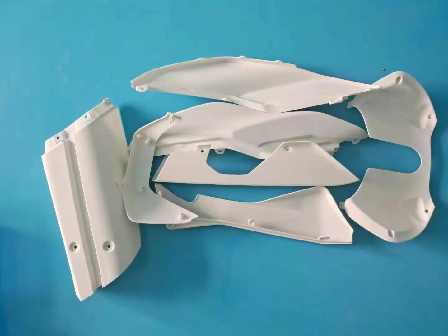
Lightweight nylon fixture with inserts and selected machined locating features.
Mockup coordinates DFM, orientation, nesting, printing, controlled cooling, depowdering, finishing, inserts, assembly and inspection as one reviewed route. Critical dimensions and the delivered finish are agreed before production.
Get an SLS quote↗PRINT / CLEAN / FINISH / VERIFYSelective Laser Sintering uses a laser to fuse polymer powder layer by layer. Surrounding powder supports the geometry before cooling, depowdering and finishing.
Dedicated supports are normally unnecessary, but every enclosed region and moving interface still needs practical powder-removal access.
Common options include PA12, PA11, selected filled nylons and flexible powders such as TPU. Availability depends on the manufacturing route.
Yes, when the selected material, geometry, environment, finish and validation plan match the application.
Yes, provided channels can be depowdered and sufficient clearance prevents intended moving surfaces from fusing.
Not automatically. Define fluid or gas, pressure, temperature, duration and allowable leakage; sealing and testing may be required.
Yes. Finishing and machining should be planned before printing because they can affect dimensions, edges and assembly fits.
Capability depends on size, material, geometry, thermal behavior, orientation and finishing. Identify critical dimensions on an engineering drawing.
No process is universally better. SLS favors functional nylon and complex support-free geometry; SLA favors visual detail, while MJF and FDM may fit different batch, surface, size or cost priorities.
STEP or STP is preferred. Include a drawing for tolerances, fits, threads, sealing, finish and inspection, plus quantity and application conditions.
Send your CAD model, drawing, quantity and application requirements. We will review material, walls, powder removal, clearances, nesting, finish and critical dimensions.