
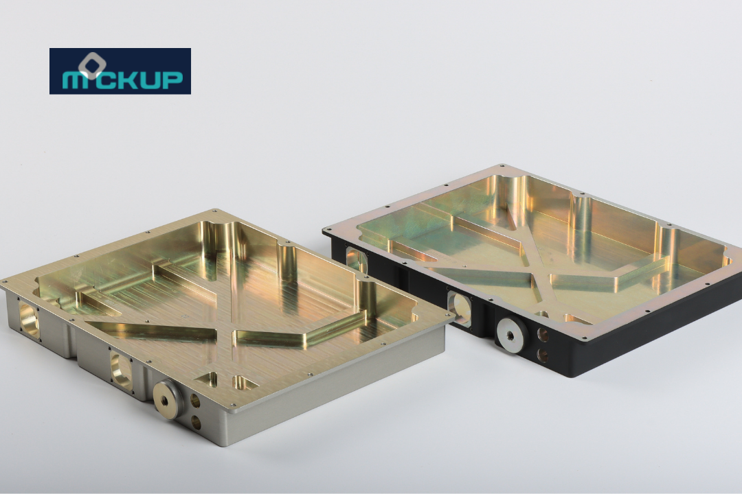
3-Axis Milling
3-axis milling for plates, brackets, pockets, housings and fixtures
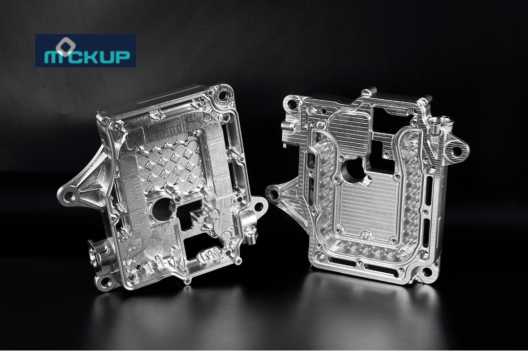
Custom CNC milling services for precision metal and plastic parts, from one-off prototypes to repeat production. Mockup reviews the model, drawing, material, tolerance, surface finish and inspection plan before selecting 3-axis, indexed 3+2, 4-axis or simultaneous 5-axis machining.
STEP, STP, X_T, SLDPRT, IGES, PDF and ZIP · Confidential handling
CNC milling is a subtractive manufacturing process that uses computer-controlled rotating cutting tools to remove material from a solid workpiece. The process creates precision features including flat surfaces, pockets, slots, holes, threads, contours and complex three-dimensional geometries. CNC milling is commonly used when parts require high accuracy, repeatability and flexible feature creation.
ROTATING CUTTING TOOLS / CONTROLLED MATERIAL REMOVALCNC milling removes material with rotating cutting tools while the workpiece is held in a controlled fixture. The correct axis strategy is the simplest route that reaches every feature, preserves critical datum relationships and leaves a practical inspection path.
3-axis milling for plates, brackets, pockets, housings and fixtures
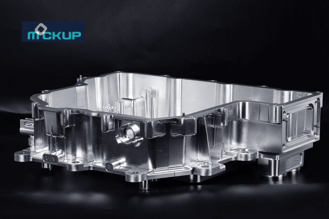
Indexed 3+2 or 4-axis machining for features distributed across multiple faces
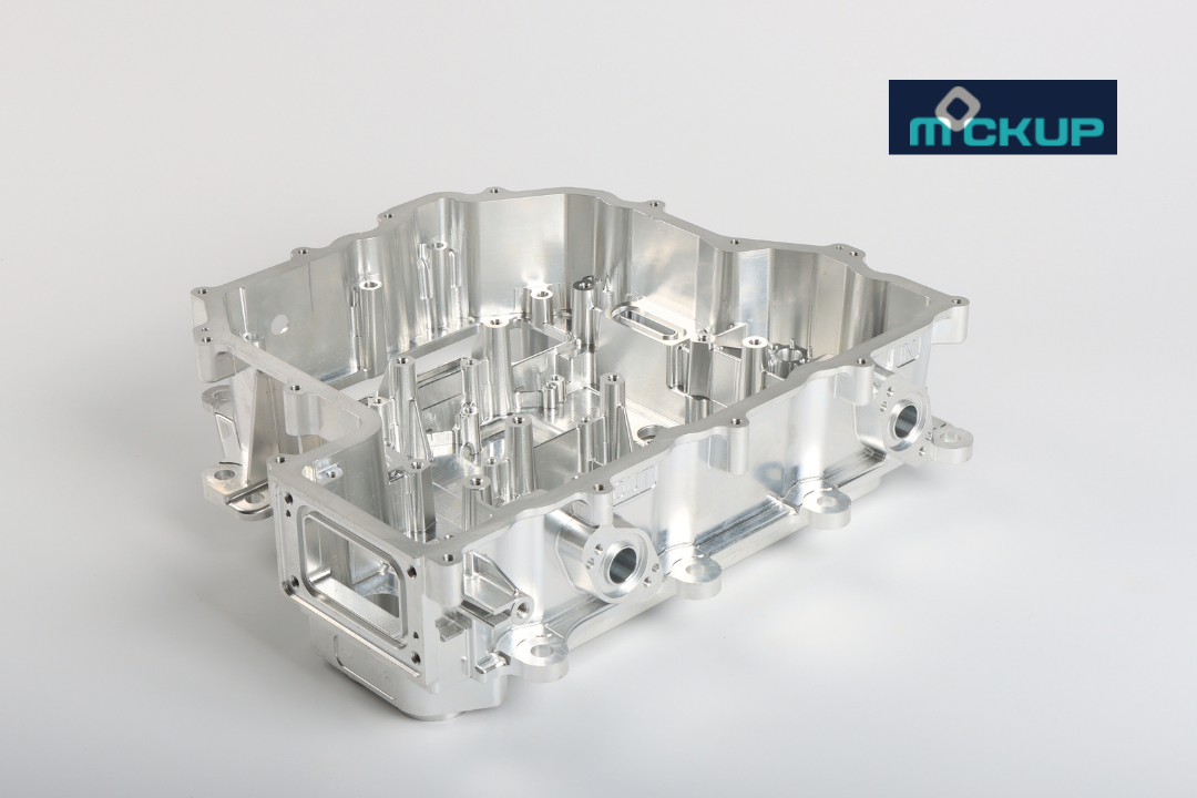
Simultaneous 5-axis milling for changing tool vectors, compound surfaces and difficult access
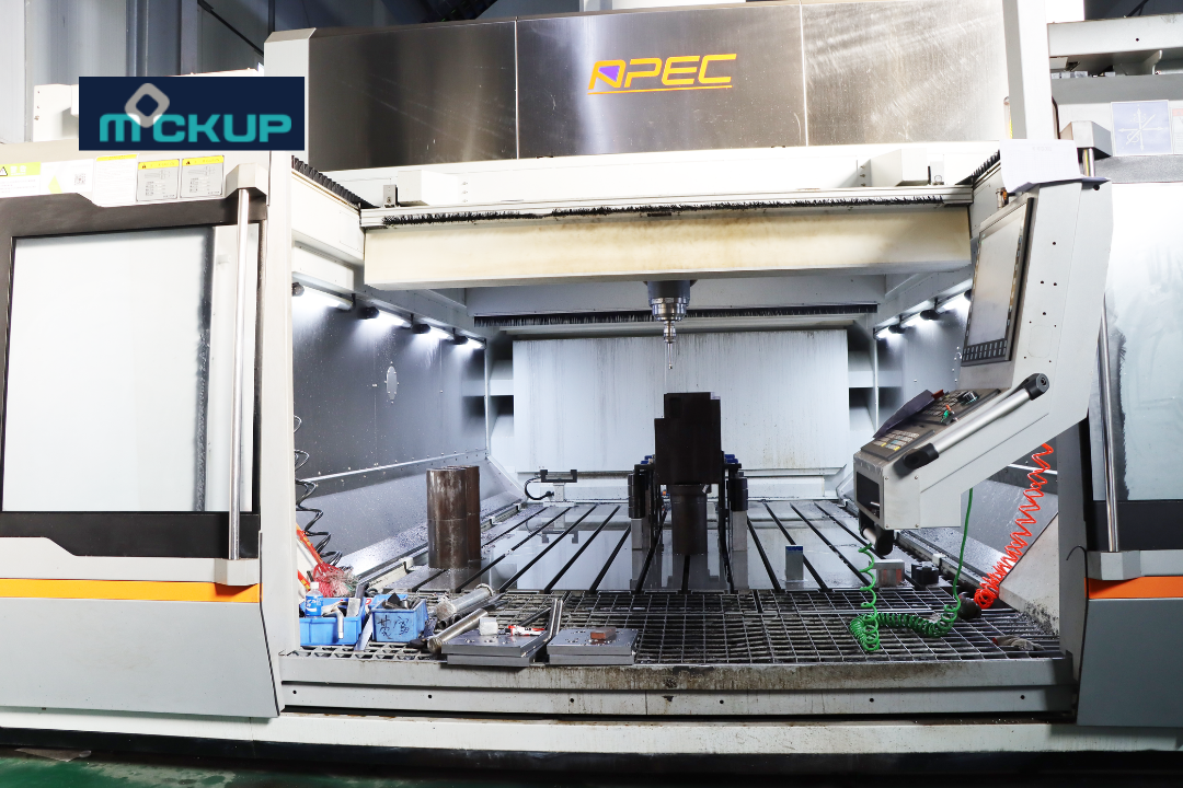
Drilling, boring, reaming, tapping, thread milling and secondary machining in the planned route
Milling is best suited to parts defined by faces, pockets, slots, bores, hole patterns, sealing surfaces and contoured profiles. Part category alone does not select the process; tool access, workholding and relationships between features determine the route.
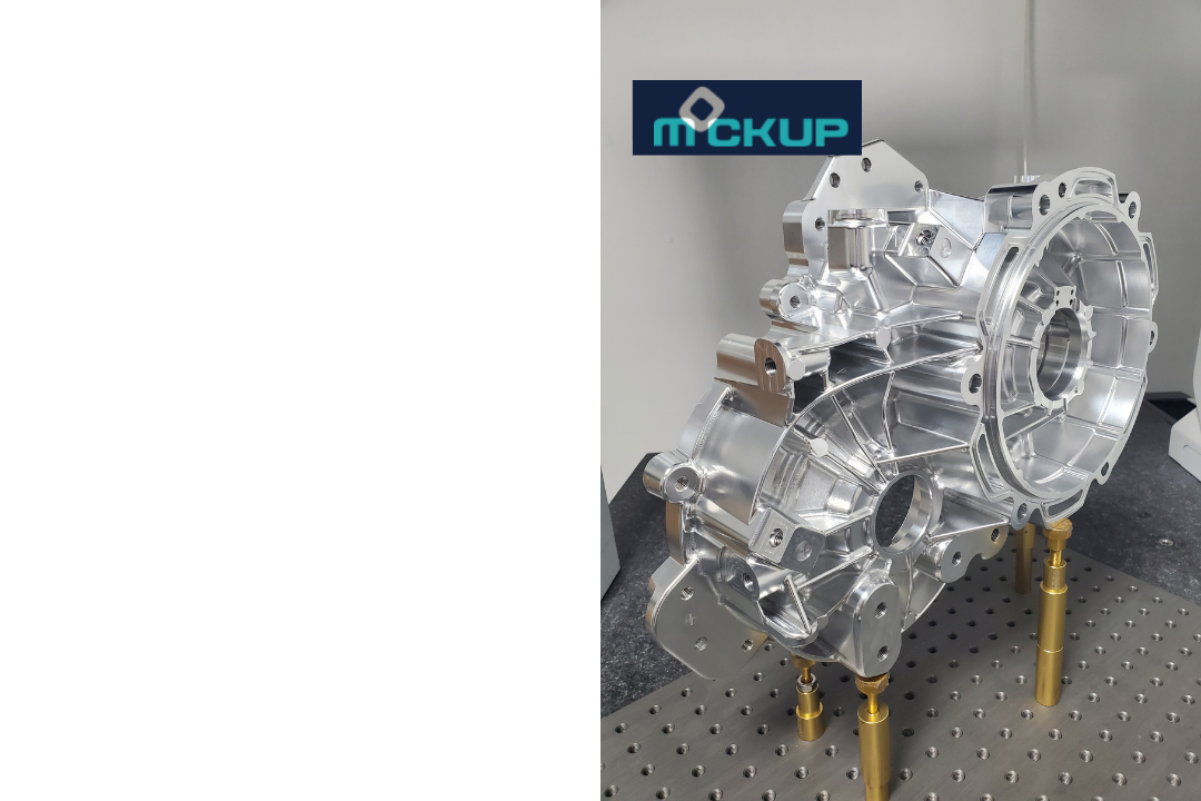
From CAD upload to manufacturing quote in minutes. The digital workflow connects project configuration with engineering review for tight tolerances, GD&T, thin walls, deep cavities, difficult access, specialty materials and advanced multi-axis machining.
Send the 3D model, controlled drawing and revision so geometry and requirements stay connected.
Select material, quantity, finishing, inspection documentation and target timing.
Manufacturing engineers review process fit, tolerances, access, workholding and project risk before release.
Approved projects move through machining, inspection, protected packaging and delivery in one workflow.
A blanket machine accuracy is not a finished-part promise. Achievable tolerance depends on feature size, material, wall stiffness, tool reach, workholding, setup transfers, thermal stability, finishing and measurement uncertainty. The approved drawing controls acceptance.
Selected linear features may be reviewed down to ±0.005 mm when geometry and inspection support it
Position, profile, flatness and perpendicularity are evaluated from the stated datum reference frame
Bores, threads and fits require the callout, mating function and inspection method
Surface roughness should be specified only where sealing, sliding, fatigue, optical or cosmetic function requires it
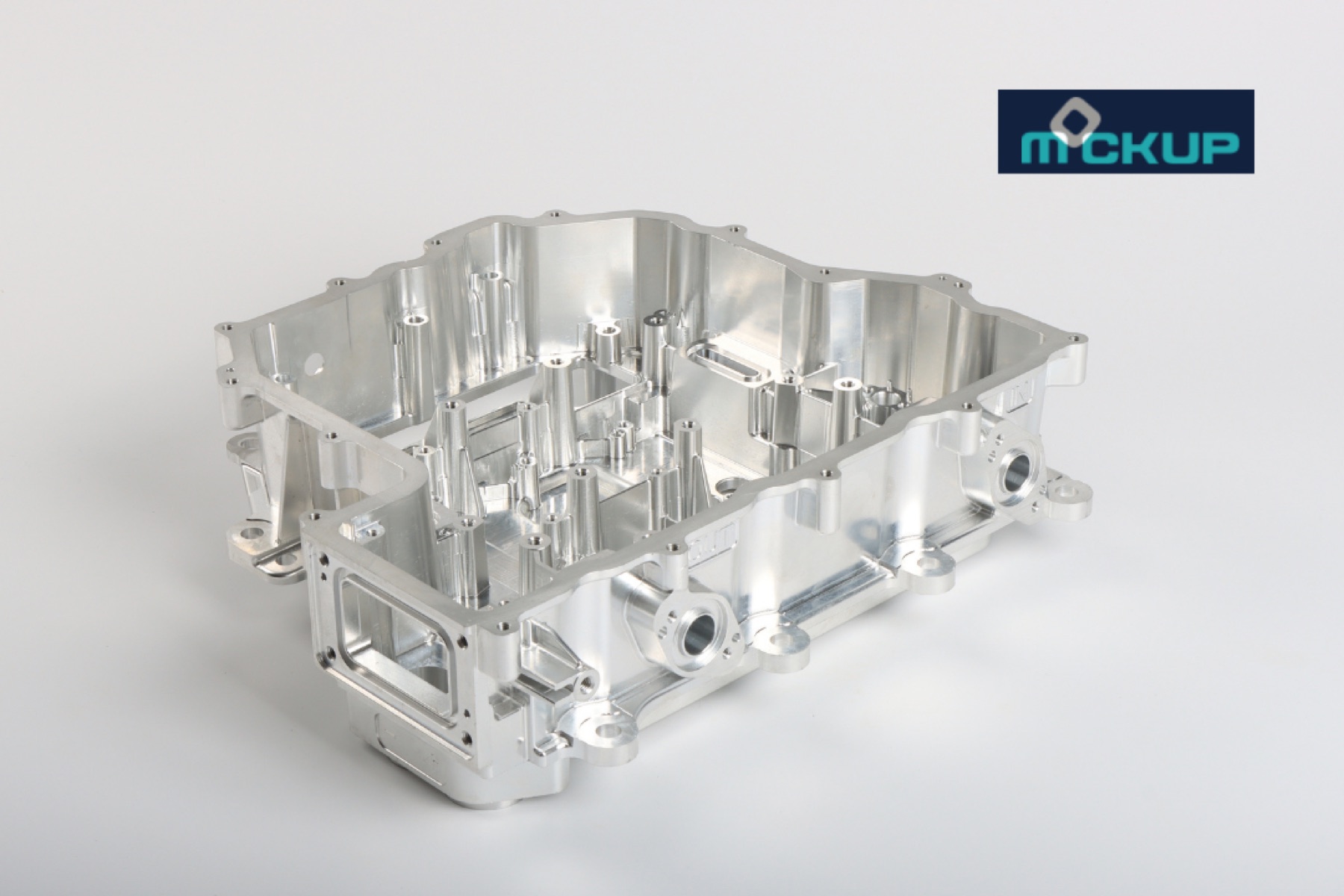
Maximum travel is not the same as usable part capacity. Fixtures, rotary tables, tool holders, probing clearance and the need to reach multiple sides reduce the working envelope. Mockup checks stock size, finished dimensions, weight, tool access and inspection access before confirming a machine route.
Provide the overall stock and finished-part dimensions
Identify faces that cannot carry clamp marks or sacrificial stock
Show critical relationships that should remain in one setup
Large, thin or tall parts require a specific distortion and support plan
Material grade, temper, stock form and condition affect cutting force, heat, chip control, tool wear, burr formation and dimensional movement. Substitutions are not made from a family name alone.
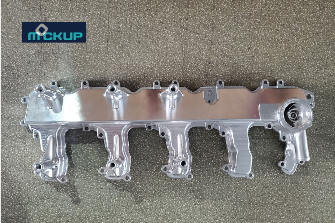
Finishing must be planned before machining because coating thickness, masking, edge condition and cosmetic preparation can change fit and final dimensions. Critical interfaces are evaluated in the delivered condition.
Aluminum
Clear, black or specified colors
Corrosion protection and appearance; allow for buildup
Aluminum
Durable technical finish
Improved wear resistance; masking may be required
Aluminum
Clear to gold
Conversion coating for corrosion protection and conductivity
Stainless steel
Natural metallic finish
Corrosion resistance or smoother surface by specification
Compatible metals
Matte or directional texture
Define cosmetic zones and protect functional surfaces
Process-compatible materials
Specified color or cosmetic finish
Mask fits, threads and electrical contact areas
The most effective milling DFM reduces long-reach cutting, weak walls, unnecessary setups and inspection ambiguity without changing functional interfaces.
Use the largest practical internal corner radius and avoid deep narrow pockets
Keep wall thickness and unsupported height appropriate to the material
Use standard hole, reamer and thread sizes with adequate tool access
Apply tight tolerances and fine surface finish only to functional features
Dimension critical features from datums that manufacturing and inspection can reproduce
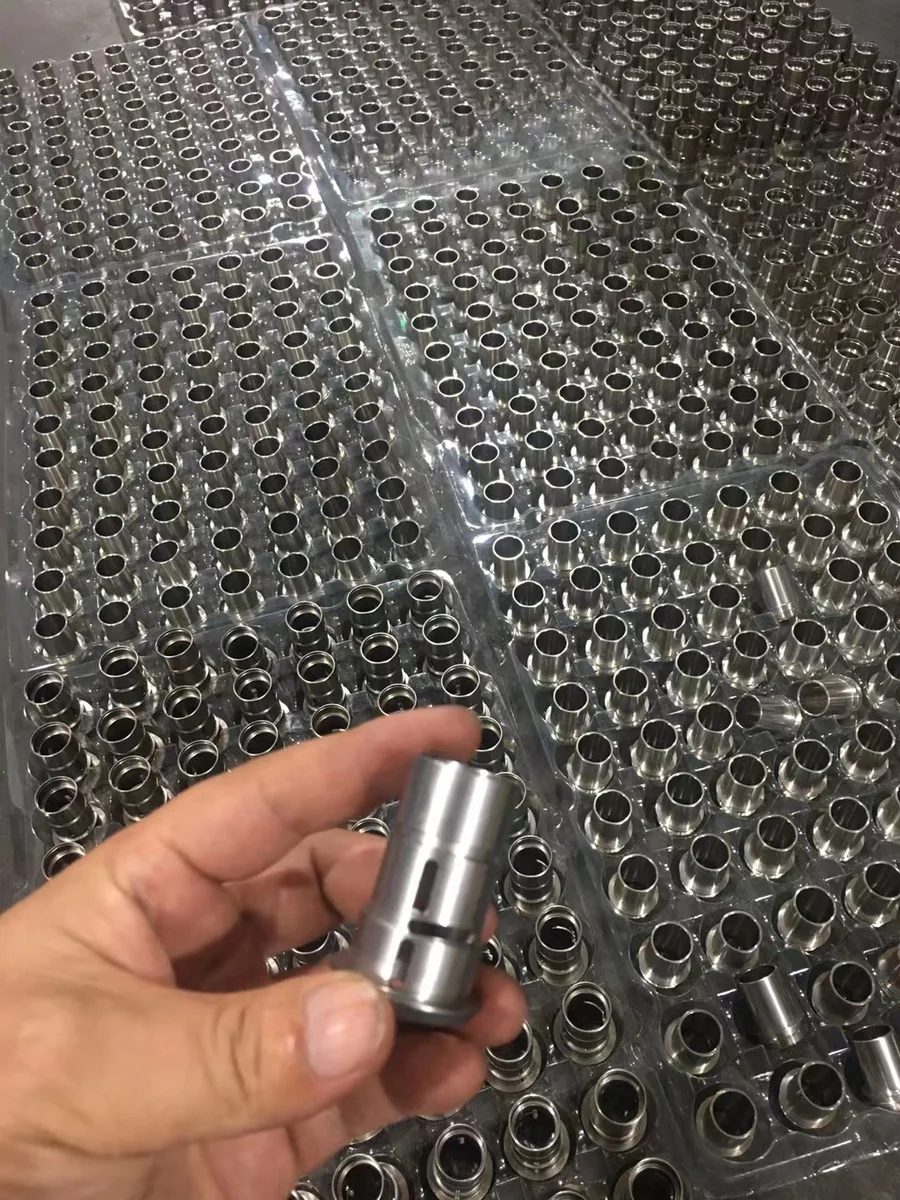
Inspection planning begins with drawing reconciliation. The model defines nominal geometry; the drawing defines datums, tolerances, threads, finishes and reporting requirements. Measurement equipment is selected for the feature and uncertainty required.
Prototype machining proves geometry and assembly fit; production machining must also control repeatability, tool life, fixture loading, inspection sampling and revision history. Approved process learning should carry into repeat orders.
One-off engineering prototypes and functional validation parts
First articles and pilot quantities before production release
Dedicated workholding and tool-life controls when volume justifies them
Controlled revisions, deviations and inspection expectations for reorders
A complete RFQ lets engineering choose the axis strategy, stock, fixture, finishing and inspection route without hiding assumptions in the price.
Get an online CNC milling quote↗STEP / STP / PARASOLID + PDF DRAWING RECOMMENDEDThree-axis milling cuts with X, Y and Z motion and is efficient for accessible prismatic geometry. Indexed 3+2 reorients the part between cuts. Simultaneous five-axis coordinates rotary and linear motion for continuously changing tool orientation or difficult access.
Tolerance is feature-specific. Selected features may be reviewed down to ±0.005 mm, but the result depends on geometry, material, workholding, tool reach, setup count, finishing and inspection method. The approved quotation and drawing control.
Send a STEP, STP or Parasolid solid model and a PDF drawing defining datums, tolerances, GD&T, threads, material, finish and inspection requirements.
Yes. Common materials include aluminum, steels, stainless steel, titanium, copper alloys and rigid engineering plastics. Exact grade, temper and stock form are confirmed during review.
Increase internal radii, reduce unnecessary pocket depth, keep features accessible, use standard holes and threads, limit tight tolerances to functional interfaces and identify only the surfaces that require cosmetic finishing.
Yes. The program, workholding, tool list, approved revision and inspection results can be retained and refined for pilot and repeat orders.