
Alloy- and route-specific
Controlled thermal condition
Specify final material condition and required records
Manufacture complex metal parts that are difficult, inefficient or impossible to produce through conventional machining alone.
Encrypted upload · Confidential handling · Engineer review
Mockup evaluates geometry, alloy, quantity, support strategy, thermal processing, machining, finishing and inspection before confirming the route.
GEOMETRY / ALLOY / POST-PROCESSING / INSPECTIONMetal additive creates the most value when the geometry itself provides a reason to print. Greater design freedom does not mean every metal component should be printed.
Layer-by-layer powder-bed fusion
Material removed from billet or bar
Complex internal and consolidated geometry
Accessible prismatic and rotational geometry
Near-net surfaces planned for finishing
Direct route to precision surfaces
Supports and powder removal must be designed
Workholding and tool access must be planned
High-value complex metal parts
Blocks, plates, shafts and housings
Economics driven by complexity and quantity
Economics driven by stock, cycle time and setups
Metal additive is strongest when geometry improves function, reduces assembly or unlocks a route conventional manufacturing cannot reach.
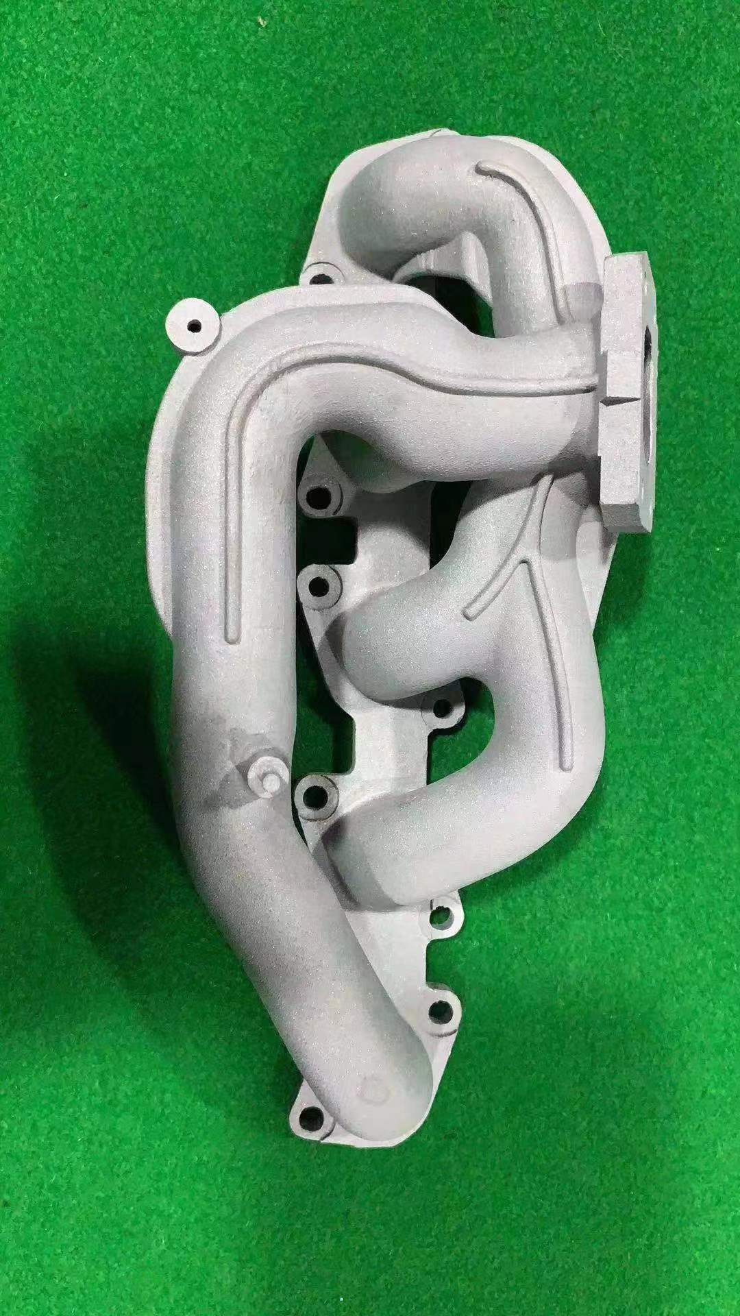
DMLS and SLM are commercial terms for closely related laser powder-bed fusion processes. Machine platform, alloy, powder specification, parameters, orientation, thermal treatment and qualification matter more than the label alone.
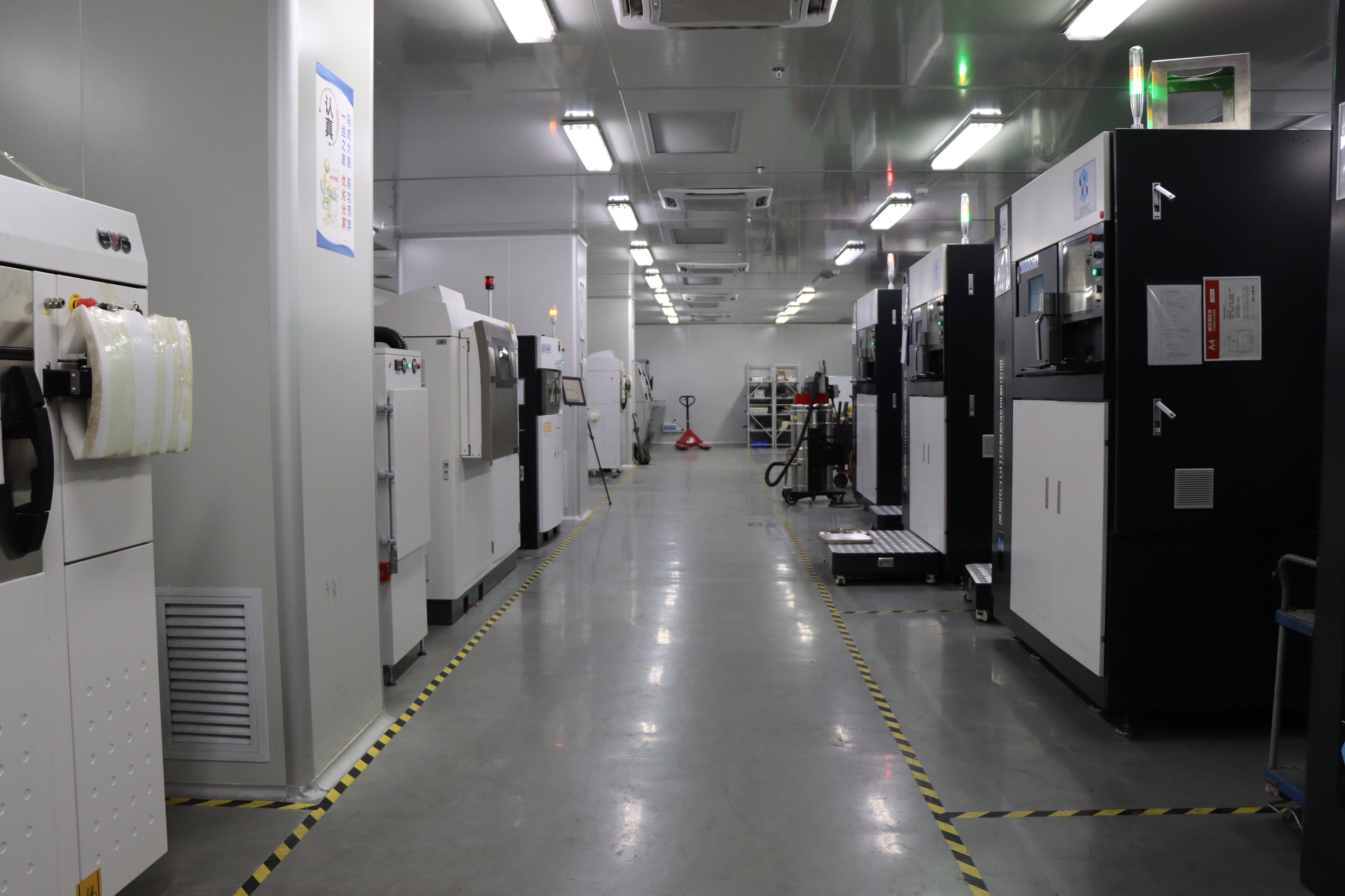
Confirm alloy, machine, parameter set and final material condition.
Build orientation, supports, thermal processing, machining and inspection belong in one plan.
Agree records and acceptance evidence around the actual application risk.
Each alloy changes support strategy, thermal management, heat treatment, machining and qualification.
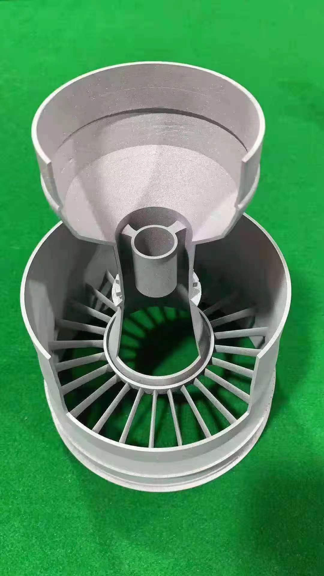
Most metal additive projects require a coordinated sequence after the build. Critical interfaces are commonly created or restored through CNC finishing.
Alloy- and route-specific
Controlled thermal condition
Specify final material condition and required records
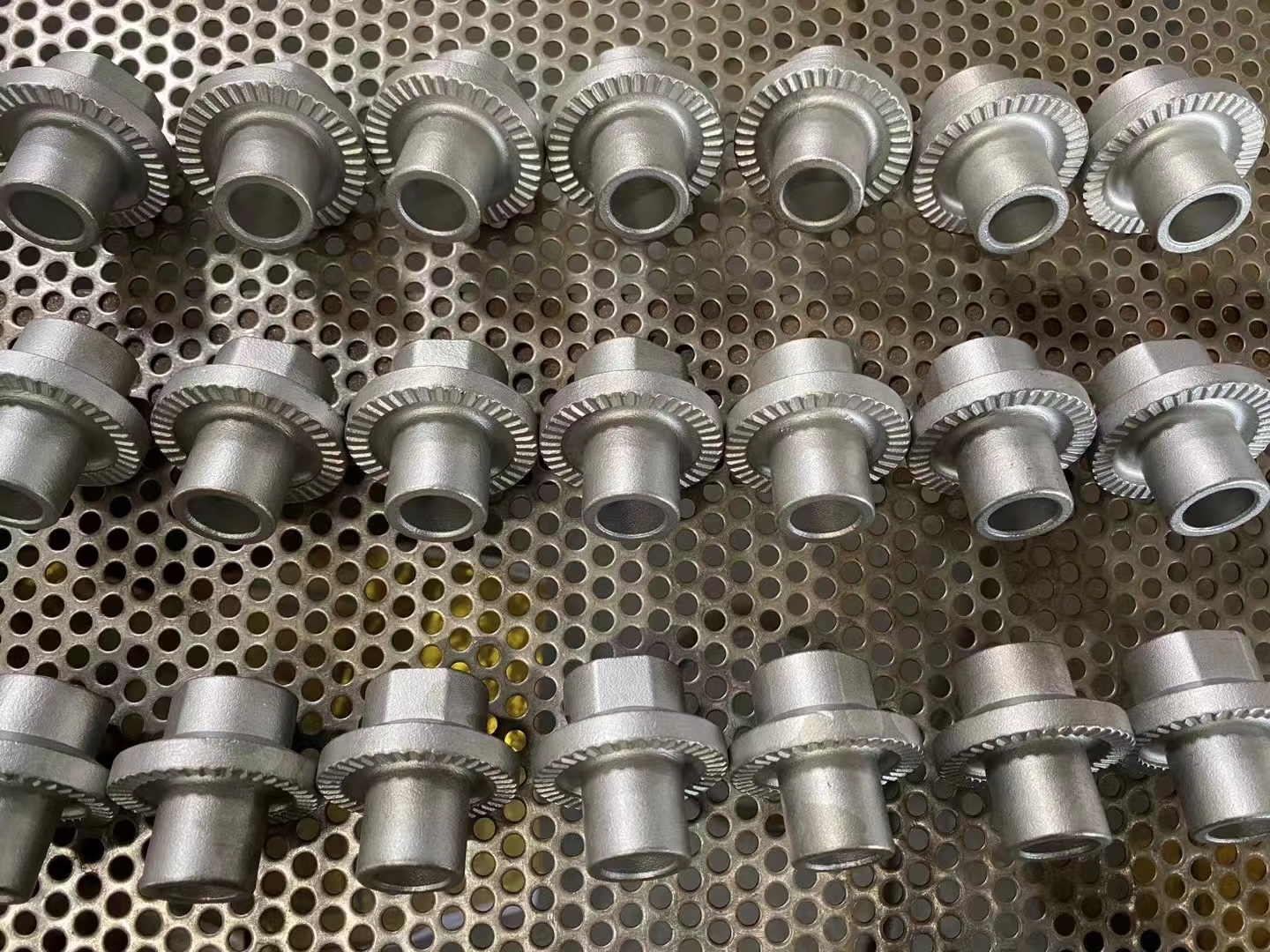
Printed metal components
Cleaned near-net surface
Design supports for access and practical removal
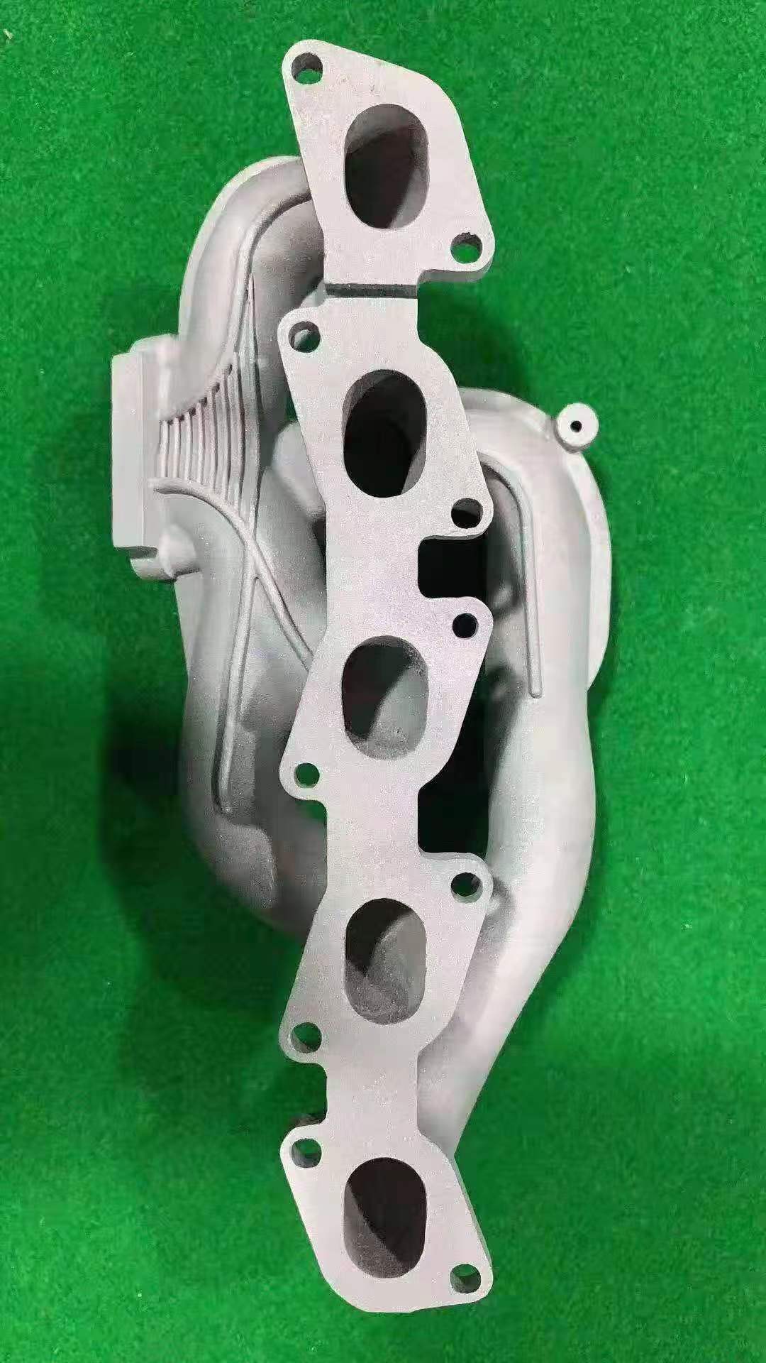
Critical bores, faces, threads and datums
Precision functional interfaces
Print machining stock around controlled features
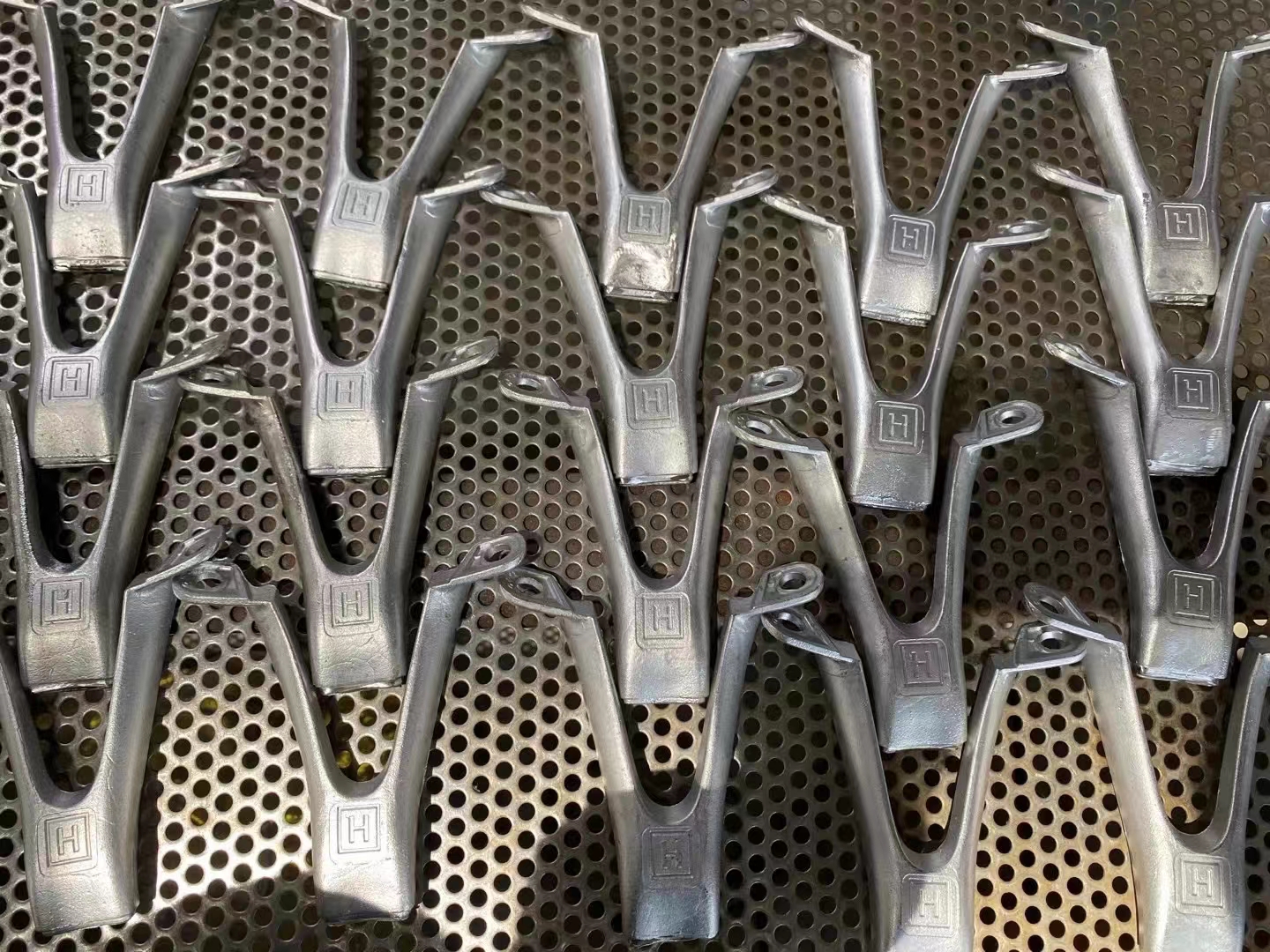
Project-dependent alloys and applications
Qualified final condition
Availability and acceptance criteria confirmed by review
Treat printing as one stage in a controlled manufacturing chain.
Review geometry, material, orientation, channels, powder evacuation, machining datums and inspection.
Select orientation, generate supports and plan allowance, nesting and traceability.
Build layer by layer under the selected process conditions and records.
Coordinate stress relief, plate separation, heat treatment, HIP and blasting as required.
Create datum surfaces, bores, threads, sealing faces and critical profiles.
Inspect against agreed dimensional, material, surface, mechanical and NDT requirements.
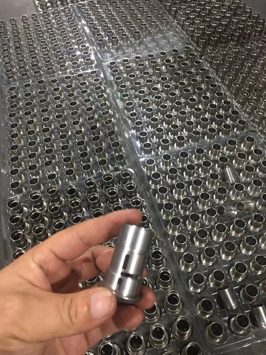
The control plan may include powder-lot traceability, machine and parameter status, build and thermal records, coupons, dimensional evidence, CT or other NDT. Scope is agreed for the actual part, alloy, equipment and route.
Good DfAM balances build success with downstream removal, machining and verification.
Resolve this requirement against the actual CAD model, alloy and complete manufacturing route.
Resolve this requirement against the actual CAD model, alloy and complete manufacturing route.
Resolve this requirement against the actual CAD model, alloy and complete manufacturing route.
Resolve this requirement against the actual CAD model, alloy and complete manufacturing route.
Resolve this requirement against the actual CAD model, alloy and complete manufacturing route.
Resolve this requirement against the actual CAD model, alloy and complete manufacturing route.
Resolve this requirement against the actual CAD model, alloy and complete manufacturing route.
Representative routes; final material, process and evidence are confirmed for each project.
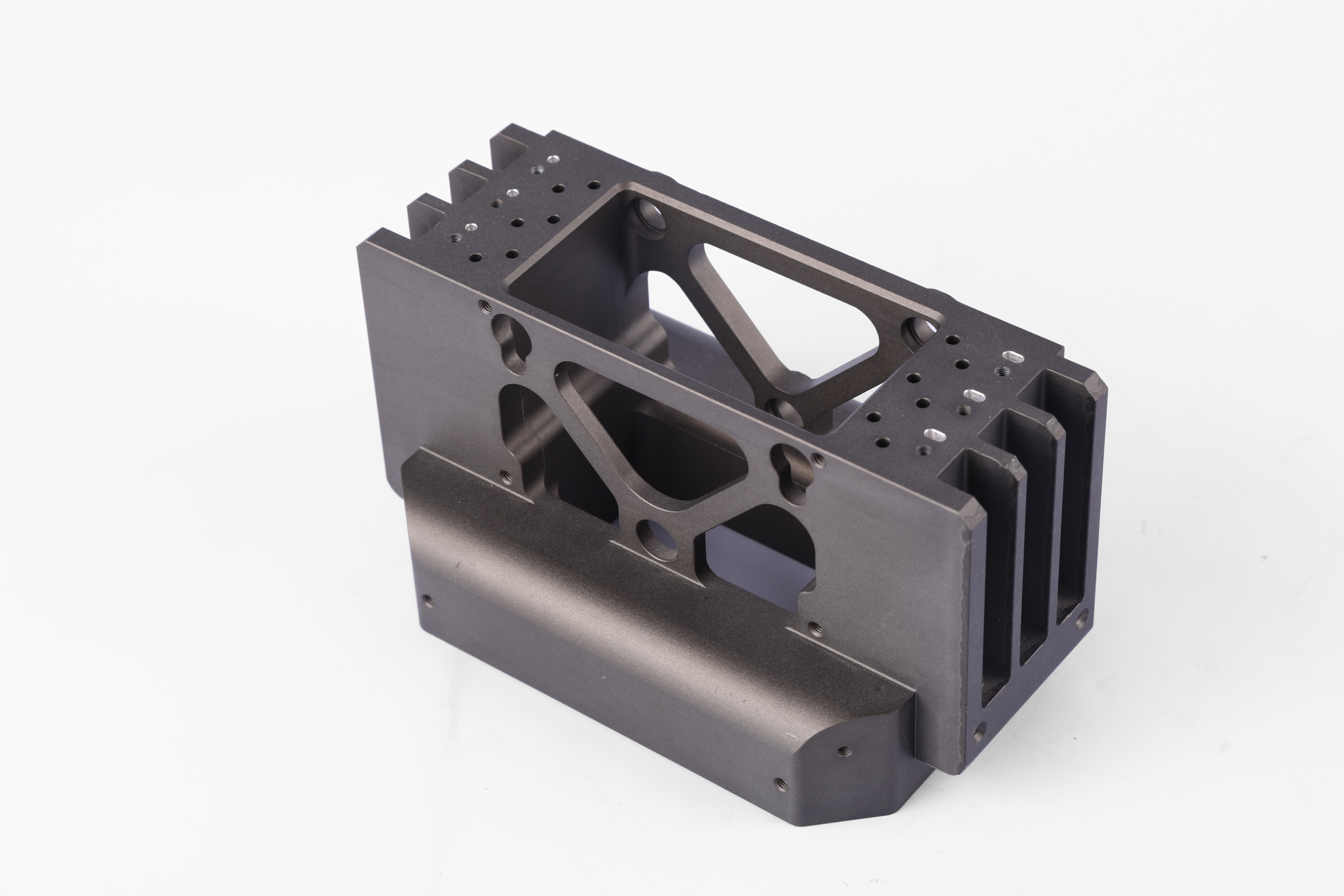
Tool or maraging steel · internal cooling geometry · heat treatment · finish-machined tooling surfaces.
Titanium or aluminum · topology-optimized mass reduction · machined mounting features.
Stainless, aluminum or nickel alloy · integrated passages · port machining · CT, flow or leak verification.
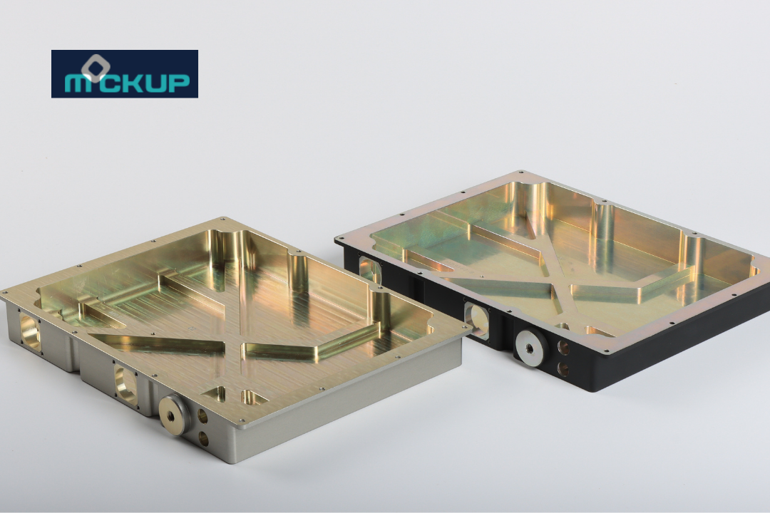
Mockup coordinates build preparation, metal printing, thermal processing, support removal, CNC finish machining, surface finishing and project-specific inspection.
Upload CAD for review↗METAL AM + CNC + VERIFICATIONThey commonly describe closely related laser powder-bed fusion approaches. The machine, alloy, powder specification, parameter set and qualification route matter more than the commercial label.
Often not. The route may include stress relief, plate and support removal, heat treatment, HIP, blasting, polishing, CNC machining and finishing.
Where CNC-level precision is required, machining allowance is normally printed around critical features and finish-machined afterward.
Depending on geometry and requirements, verification may use CT, flow, pressure, leak or another method planned during design.
Send a STEP or STP model and drawing, plus material, quantity, application, critical dimensions, surfaces, thermal treatment, finish and inspection requirements.
We will compare metal printing, CNC machining, hybrid AM + CNC and other suitable routes from geometry, material, quantity, interfaces and inspection.