
CAD and drawing requirements reconciled before programming
CAD and drawing requirements reconciled before programming
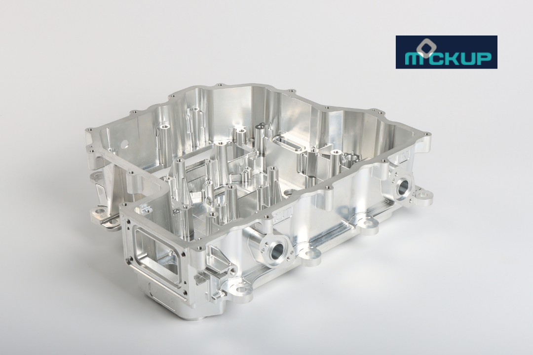
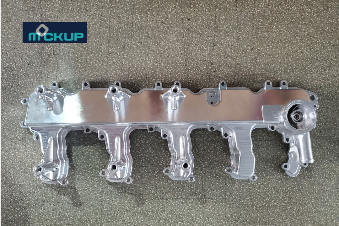
5-axis CNC machining services for complex, high-precision metal and plastic components—from one-off prototypes and engineering validation parts to low-volume and repeat production.
STEP, STP, X_T, SLDPRT, IGES, PDF and ZIP · Confidential handling
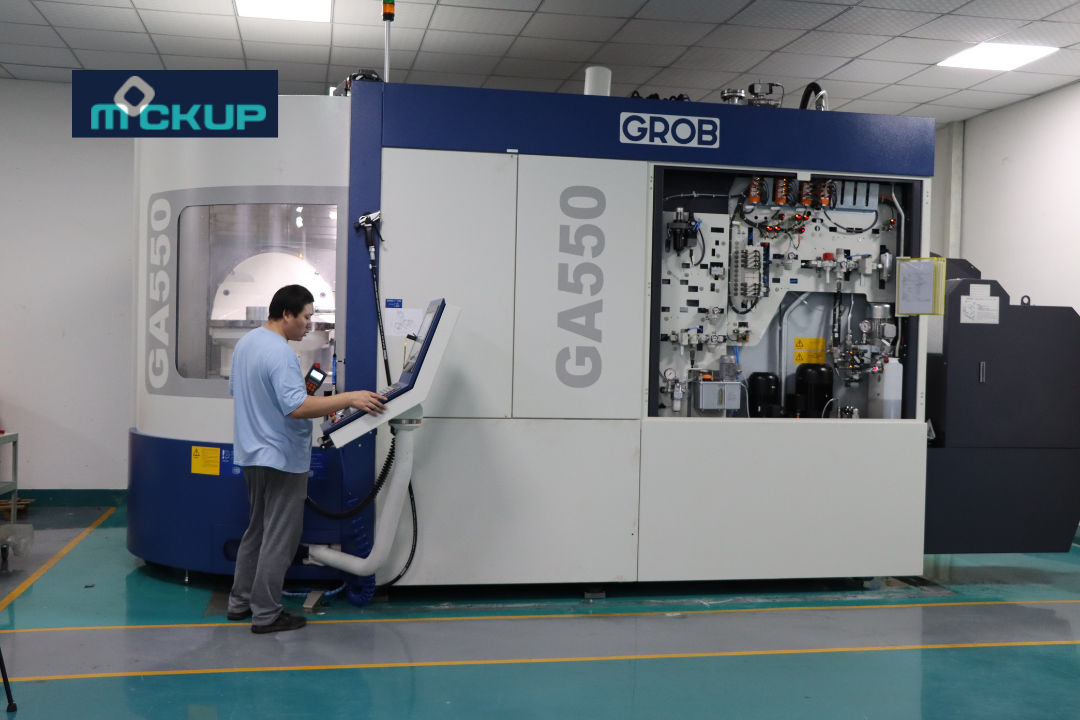
The process starts with a 3D CAD model and, when required, a technical drawing defining critical dimensions, GD&T, surface roughness, threads, materials, finishes and inspection requirements. CAM software converts the geometry into coordinated linear and rotary toolpaths.
A 5-axis CNC machine combines X, Y and Z linear motion with two rotational axes. The tool, workpiece or both can change orientation so several faces and angles are machined within one controlled setup.
Access several faces and compound angles in fewer setups
Reduce cumulative variation from repeated datum transfers
Use shorter, more rigid tools for deep or angled features
Control related bores, faces, holes and contours from a common setup
Support prototypes, engineering validation and repeat production
Review every quote for the simplest reliable manufacturing route
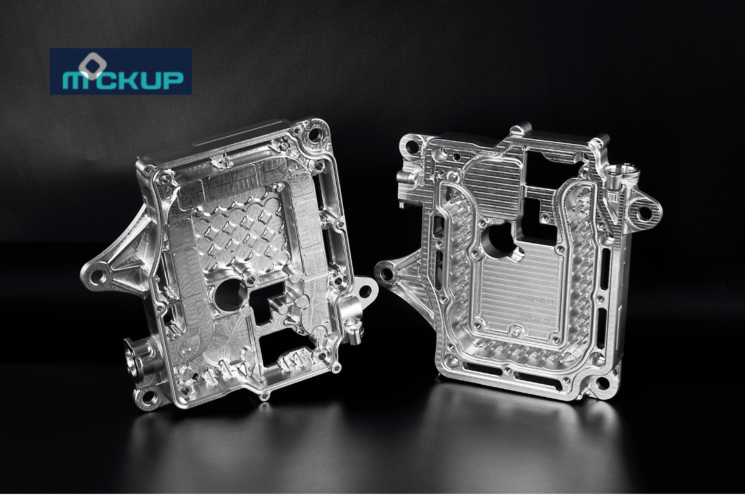
The process starts with a 3D CAD model and, when required, a technical drawing defining critical dimensions, GD&T, surface roughness, threads, materials, finishes and inspection requirements. CAM software converts the geometry into coordinated linear and rotary toolpaths.
CAD and drawing requirements reconciled before programming
CAM toolpaths planned around access, rigidity and chip evacuation
Machine simulation used for rotary travel and collision review
Workholding protects critical datums while leaving tool access
In-process checks manage tool wear and dimensional drift
Final inspection follows the drawing and agreed quality plan
Simultaneous machining moves linear and rotary axes continuously during cutting. Indexed 3+2 machining uses rotary axes to position the part, locks the orientation, then cuts with X, Y and Z. Both can reduce fixtures; they solve different geometry and cost problems.
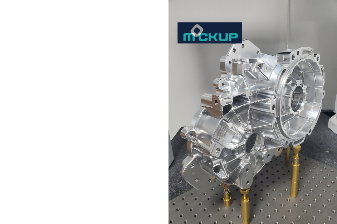
Rotary axes position, then lock
Linear and rotary axes move together
Multi-face planar features
Continuously changing geometry
Controlled finish at fixed orientations
Excellent surface continuity
Lower programming complexity
Fewer setups for suitable parts
Housings, brackets, manifolds
Impellers, contours, compound surfaces
Generally lower total process cost
Higher programming and simulation investment
A part does not need 5-axis machining merely because it looks complicated. The decision depends on which features create manufacturing risk and whether additional axis motion removes that risk.
More axes do not automatically create a better manufacturing process. Simple plates, spacers, flanges, brackets and accessible prismatic components are often produced more efficiently on 3-axis equipment.
Unnecessary 5-axis use can add CAM programming time, machine cost, simulation requirements and setup complexity without improving the drawing result.
If a 3-axis or indexed 3+2 route can meet the requirements reliably, Mockup may recommend it instead. The objective is not to sell machine time; it is to select the right process for the part.
Accessible planar geometry with few machining directions
Loose relationships between features on separate faces
Simple rotational parts better suited to CNC turning
Programs where extra simulation adds cost but no measurable benefit
Parts whose primary constraint is material stability rather than access
Components that remain blocked by enclosed undercuts or fixture obstruction
Our manufacturing network supports prototype and production machining across a wide range of part sizes, materials and geometric requirements. Final capability depends on machine configuration, geometry, stock, workholding, tolerance stack and inspection requirements.
For critical dimensions, do not rely on a general website tolerance. Upload the drawing so engineering can evaluate each requirement against the actual feature size, material and machining strategy.
CNC processes
3-axis, 4-axis, indexed 3+2 and simultaneous 5-axis machining
Materials
Metals, engineering plastics and specialty alloys
Material library
250+ materials and grades
Prototype quantity
From one part
Production
Low-volume and repeat production
Drawing-defined tolerances
Engineering review required
GD&T
Supported
Threads
Metric, UNC, UNF and drawing-defined specifications
Surface roughness
Drawing-defined options available
Inspection
Dimensional inspection and CMM
Documentation
Project-dependent inspection and material records
CAD input
STEP and common manufacturing CAD formats
Tolerance capability is not one number that applies to every feature. Material stability, feature size, wall thickness, cutter length, tool access, machine configuration, fixture rigidity, thermal conditions and the inspection method all affect the result.
Explicitly identify critical dimensions on the technical drawing
Use general tolerances only for genuinely non-critical dimensions
Plan datum structures around manufacturing and inspection access
Evaluate thin walls and asymmetric stock removal for distortion
Define the inspection method for critical multi-axis relationships
Inspect finished-condition dimensions after coating where required
Design choices made before quotation strongly affect machining time, tool access, achievable quality and total cost. Five-axis orientation improves access, but it does not remove the physical limitations of cutters, holders, workholding or material behavior.
Avoid unnecessarily deep cavities: reduce depth, increase width or provide another access direction
Use practical internal corner radii so larger, more rigid cutters can remove material efficiently
Avoid excessively thin walls unless their function justifies vibration and distortion risk
Keep tolerances functional; reserve tight requirements for fit, motion, sealing and alignment
Define critical datums clearly so feature relationships are manufacturable and inspectable
Check whether a real cutter and holder can reach deep slots, narrow openings and hidden surfaces
Material selection should consider machinability, dimensional stability, heat generation, tool wear, surface requirements and post-processing—not strength alone. Exact grade, condition, product form and certification are confirmed during quotation.
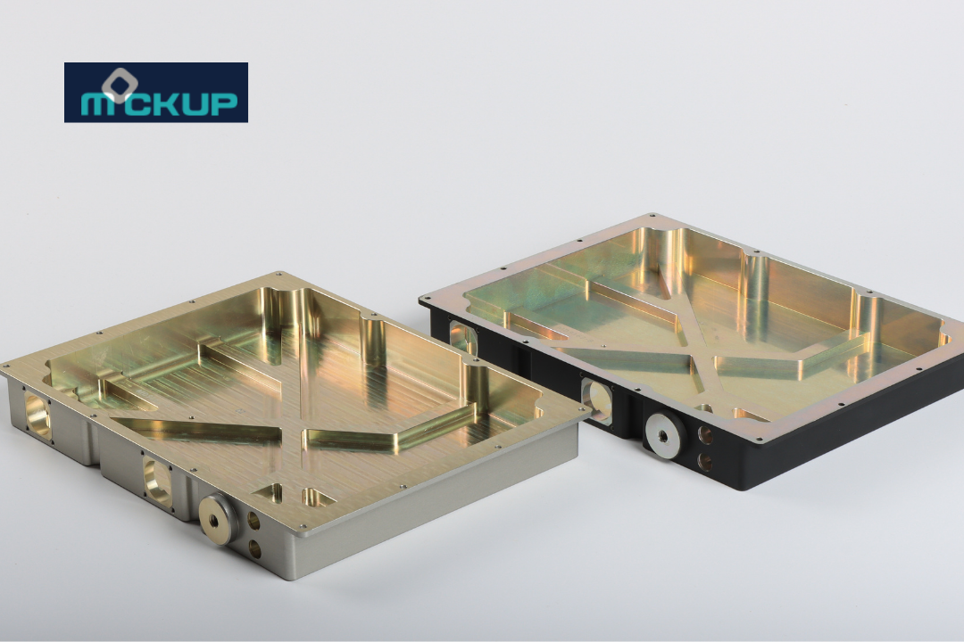
The correct grade is the one that satisfies the functional environment while remaining controllable through machining, finishing and inspection.
6061 aluminum — versatile machining, corrosion resistance and general mechanical use
7075 aluminum — higher strength for aerospace and high-performance structures
304 / 316L stainless — industrial, medical, fluid and corrosion-resistant components
17-4 PH stainless — higher-strength mechanisms and demanding hardware
Titanium Grade 5 — aerospace, medical, marine and high-performance robotics
Copper and brass — electrical, thermal, fitting, valve and instrumentation components
Inconel 625 / 718 — aerospace engines, energy, turbine and oil-and-gas equipment
Engineering plastics — insulation, semiconductor, chemical and lightweight mechanisms
Finishing can add corrosion resistance, wear performance, appearance or controlled electrical behavior. Masking, cosmetic zones, thread protection and coating-sensitive dimensions should be defined before machining begins.
Metals and engineering plastics
Natural toolpath appearance
Fastest route; define roughness where functional
Aluminum and compatible metals
Uniform matte texture
Often used before anodizing; mask critical fits
Aluminum alloys
Clear, black and specified colors
Type II or hard anodize; account for coating buildup
Stainless steel and compatible alloys
Process-specific appearance
Confirm masking, certification and finished dimensions
Complex 5-axis surfaces require coordinated decisions about tool diameter, tool geometry, toolpath direction, stepover, feed rate, spindle speed, cutter engagement, rigidity and material behavior.
Continuously changing tool orientation can improve access and contact on sculpted geometry, but surface quality still depends on scallop control, transition blending, tool wear and stable engagement.
Define which surfaces are functional, sealing, aerodynamic or cosmetic so programming and inspection effort is concentrated where it creates value.
Choose cutter geometry for the surface and material
Control stepover and scallop height on contoured faces
Keep tools as short and rigid as access permits
Simulate holder and machine-head clearance
Blend toolpath transitions on visible or functional surfaces
Define roughness and cosmetic acceptance only where required
A complete RFQ lets engineering select the axis strategy, workholding, tooling and inspection route without hidden assumptions.
Upload CAD for a quote↗STEP / PARASOLID + PDF DRAWING RECOMMENDEDIt is a subtractive process combining three linear axes with two rotational axes so a cutter can reach several faces, angles and contours within one controlled setup.
In 3+2 machining the rotary axes position the part, then remain fixed while X, Y and Z cut. In simultaneous machining, linear and rotary axes move together while the cutter is engaged.
Use it when compound angles, continuous contours, deep access, shorter-tool requirements or critical relationships across several faces create measurable manufacturing value.
Accessible plates, brackets, spacers, flanges and other prismatic parts are often faster and less expensive on 3-axis equipment when multiple orientations do not control function.
Machine and programming rates are higher, but total part cost may be lower when one controlled setup replaces multiple fixtures, inspections and handling steps.
Tolerance is feature-specific. Geometry, material stability, wall thickness, tool reach, workholding, thermal conditions and the agreed inspection method must be reviewed against the drawing.
Options include aluminum, stainless and alloy steels, titanium, copper, brass, nickel superalloys and a broad range of engineering plastics. Exact grades and stock conditions are confirmed during review.
Send a STEP or Parasolid model plus a dimensioned PDF drawing. Native CAD can help when complex surfaces or assemblies require deeper review.
Yes. CMM and project-specific dimensional documentation can be included when identified in the RFQ and approved quality plan.