
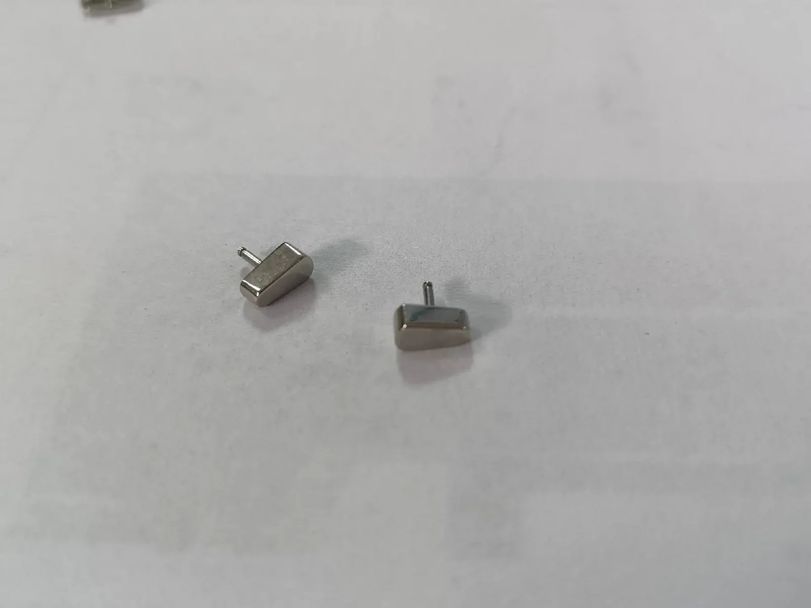
Sliding-Headstock Turning
Guide-bushing support keeps the cutting zone close to material support for slender diameters and controlled surfaces.
Produce slender, small-diameter components with the material supported close to the cutting zone. Mockup routes Swiss-type machining for tight feature relationships, multi-operation efficiency and consistent production of precision parts.
STEP, STP, X_T, SLDPRT, IGES, PDF and ZIP · Confidential handling
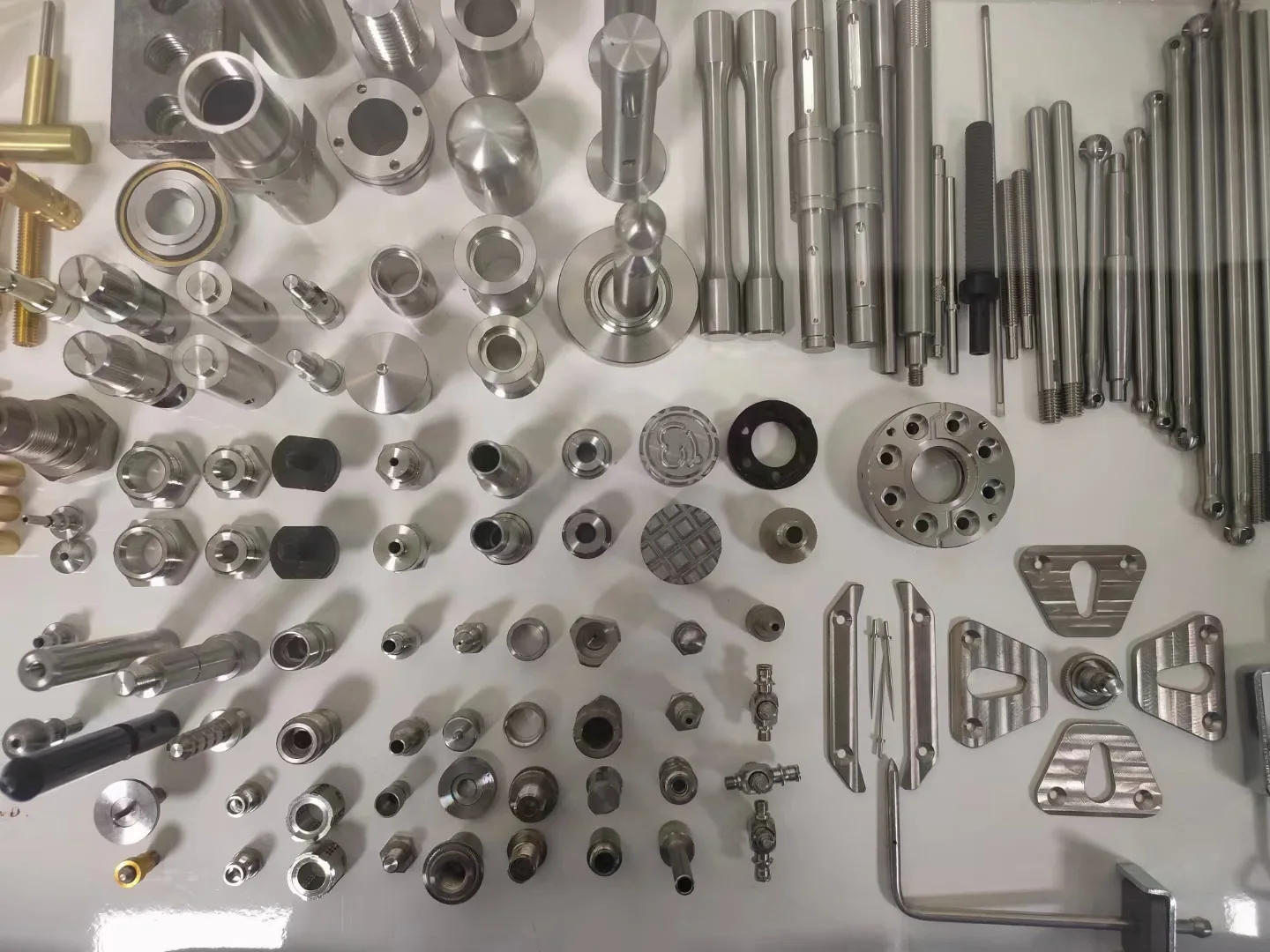
Swiss machining feeds bar stock through a guide bushing with a sliding headstock so the material is supported close to the cutting tool. This short unsupported distance helps control small diameters and slender features while turning, drilling, threading, live-tool milling and back working can be coordinated in one production route.
GUIDE-BUSHING SUPPORT / MULTI-OPERATION SMALL PARTSA Swiss-type lathe uses a sliding headstock and guide bushing to support bar stock close to the tool. Shortening the unsupported cutting distance reduces deflection and vibration, which is valuable for small-diameter, long and intricate parts.
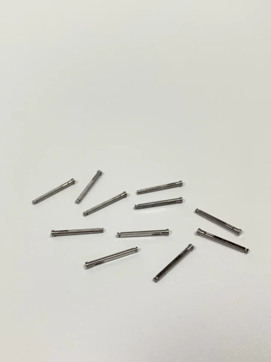
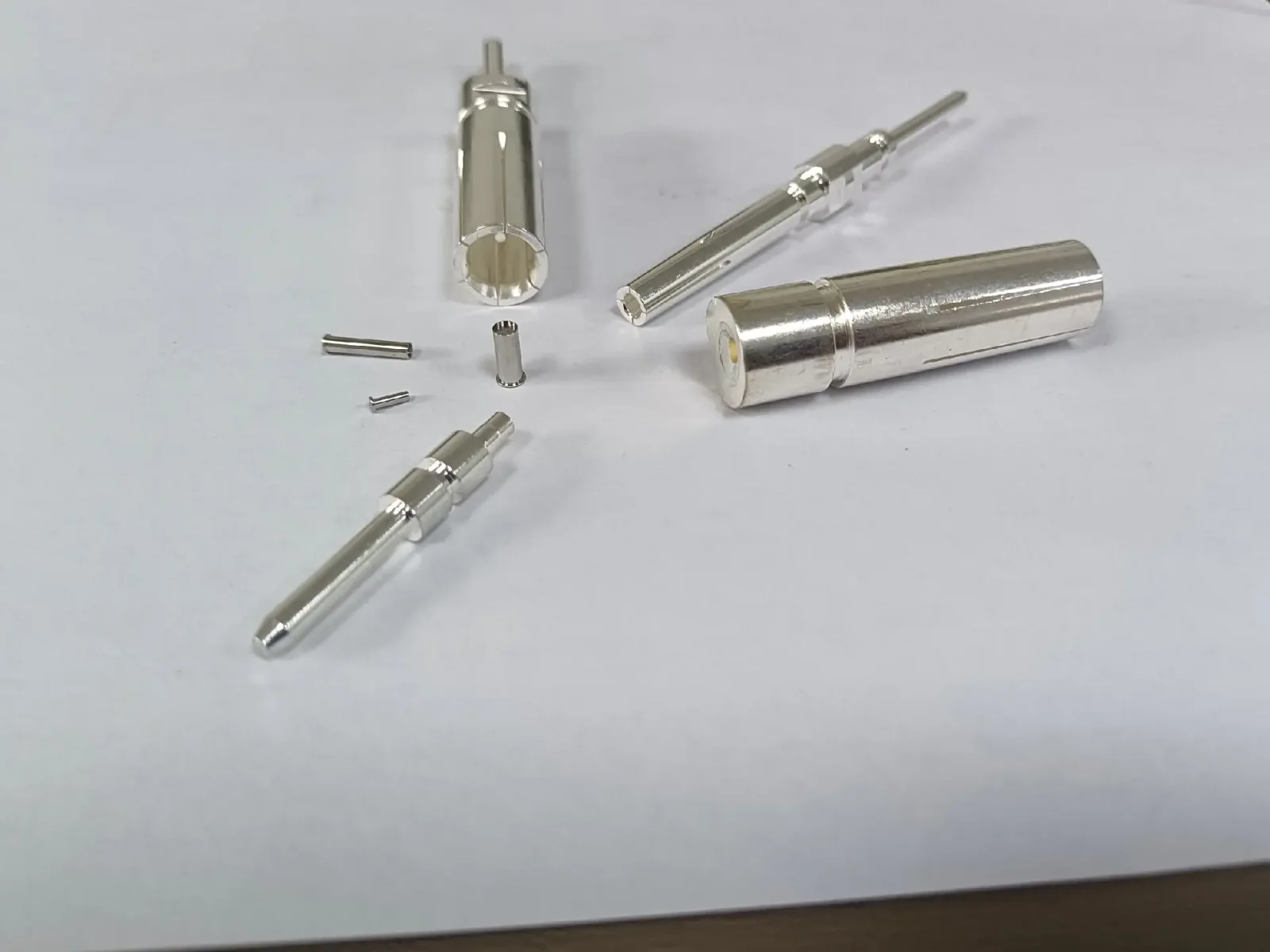
Sliding headstock through guide bushing
Fixed chuck with unsupported extension
Small, slender and feature-dense parts
Larger, shorter and simpler rotational parts
Support close to the cut reduces deflection
Direct route for chuck-friendly geometry
Multiple operations consolidated in-cycle
Secondary operations planned separately
High length-to-diameter ratios
Low-to-moderate length-to-diameter ratios
Setup justified by complexity or repeat demand
Efficient for simple parts and lower setup demand
The selected Swiss-type configuration consolidates operations only where guide-bushing support, tool access, sub-spindle capability and production economics create measurable value.
Guide-bushing support keeps the cutting zone close to material support for slender diameters and controlled surfaces.
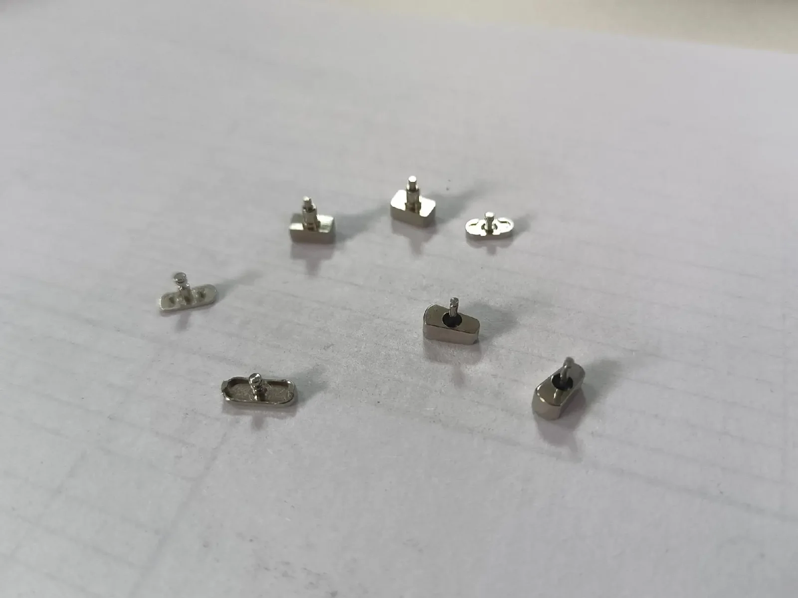
Axial and radial drilling, milling, flats, slots and cross-holes produced in the planned cycle.
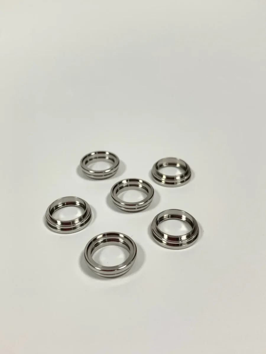
Back-side operations completed in-cycle where machine configuration and part geometry allow.
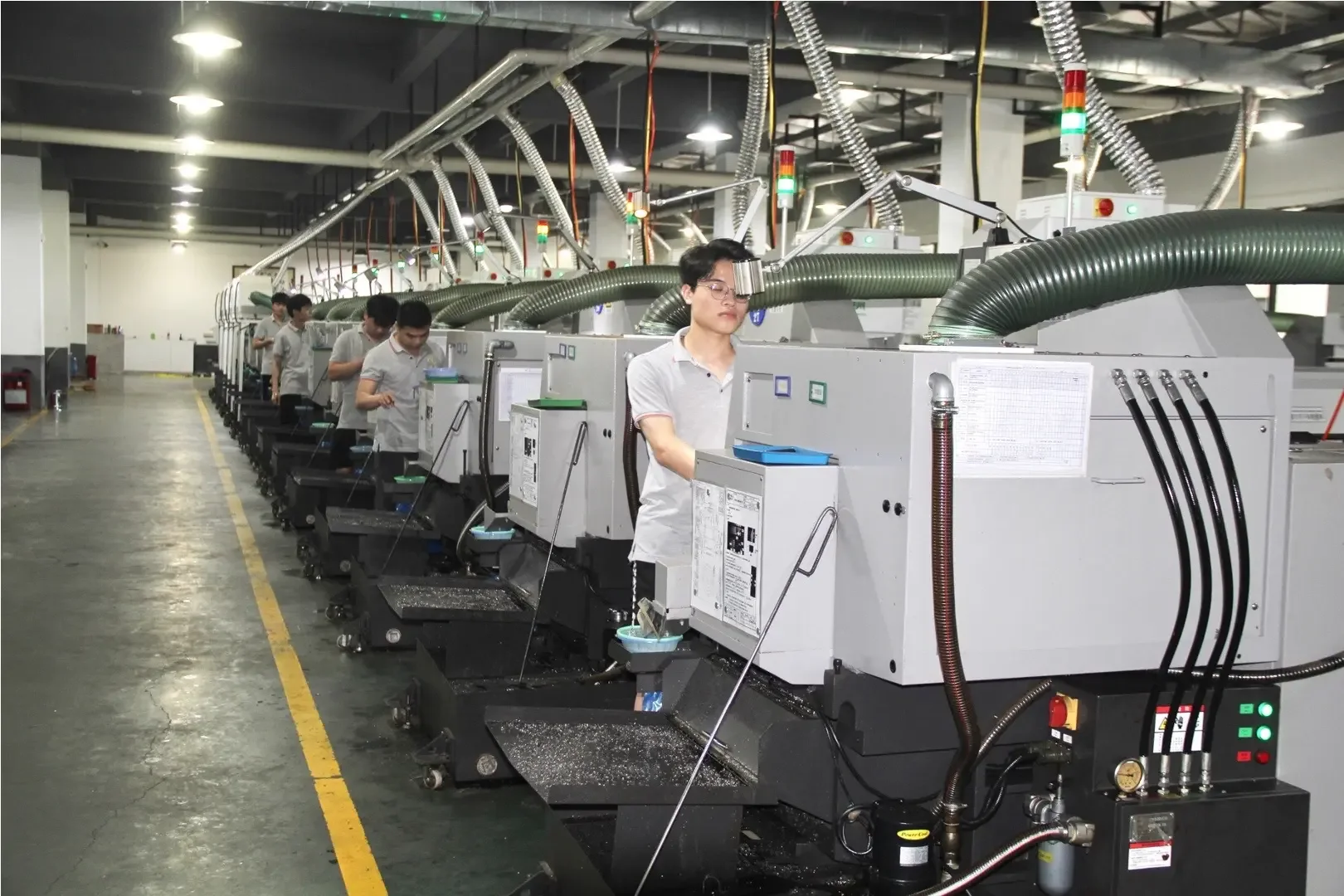
Automated bar feeding and validated tooling support consistent repeat releases and higher quantities.
Swiss tolerances are feature-specific. Diameter, length, concentricity, runout, thread and surface requirements are evaluated together with material, bar straightness, guide-bushing fit and measurement capability.
Bar / part diameter
Ø0.5–42 mm
Maximum practical length
Up to 600 mm by geometry and support review
Length-to-diameter guidance
Up to 20:1 standard routing; up to 40:1 by engineering review
Standard tolerance
ISO 2768-m for untoleranced dimensions
Tightest reviewed tolerance
Down to ±0.002 mm on selected features
Minimum feature / drill
Ø0.2 mm by depth, material and tool-life review
Surface roughness
Ra 0.8 μm standard target; down to Ra 0.4 μm on selected surfaces
Thread capability
Metric and imperial; class and gauge by drawing
Live tooling
Axial and radial drilling, milling, flats, slots and cross-holes
Sub-spindle / back working
Available where machine configuration and geometry support it
Typical quantity
1–100,000+ parts; economics reviewed by release pattern
Inspection
Optical, CMM, gauges and surface measurement by feature and plan
Swiss machining economics change with setup, bar preparation, cycle consolidation and release volume. Mockup compares the total route rather than forcing every small part onto a Swiss machine.
Prototype & Process Validation — validate geometry, material behavior, tool access and measurement before a larger run
Bridge Production — support pilot builds, market validation and supply transitions with controlled revisions
Repeat & Higher-Volume Production — use bar-fed automation, validated tooling and stable process controls for consistent releases
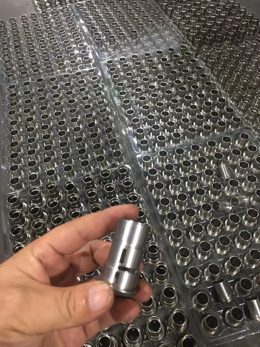
Small parts may contain features that are difficult to access or measure. Mockup confirms the measurement method, sampling level and required evidence before production rather than assuming every callout can be verified the same way.
Straightness, diameter consistency, condition, machinability and certification can matter as much as nominal material grade in Swiss production. Stock requirements are confirmed during review.
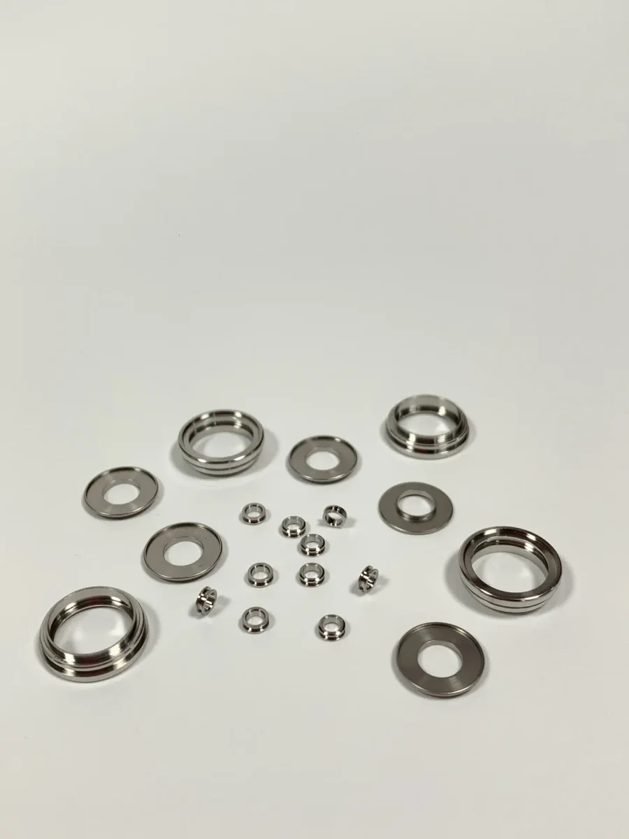
Effective Swiss DFM keeps features supported, tools accessible, chips controlled and miniature requirements measurable throughout a repeat production cycle.
Define functional diameters, fits and datum relationships clearly
Use standard bar diameters where possible to reduce material and preparation cost
Specify complete thread requirements including class, depth and gauge
Avoid fragile features that leave inadequate support near the cutting zone
Review deep holes, small drills and high length-to-diameter features for chip evacuation and tool life
Consolidate cross-holes, flats and slots only when live-tool access is practical
Plan a realistic measurement method for miniature internal and external features
Share annual demand and release pattern so setup economics can be evaluated
Industry use does not by itself imply regulatory approval. Material, process validation, traceability and documentation are confirmed to the specific project requirement.
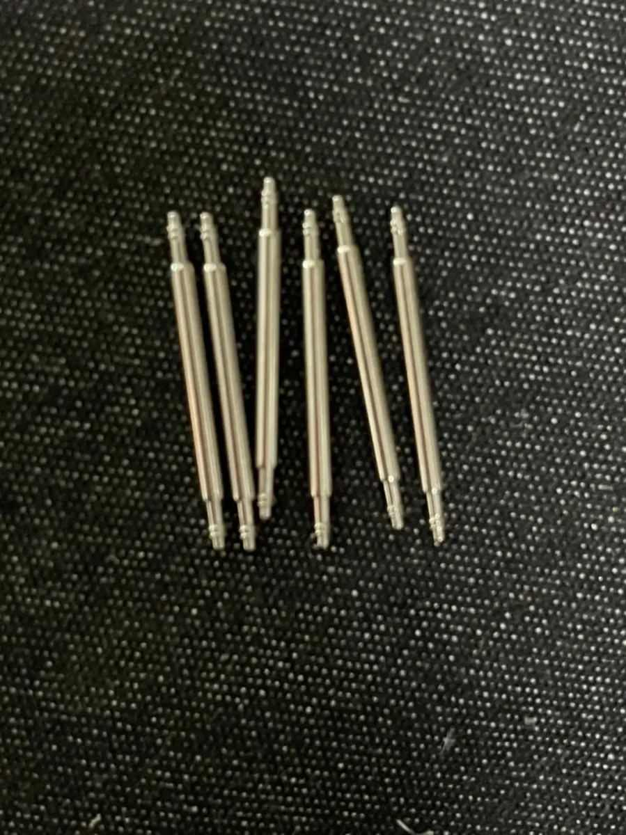
Representative programs show how guide-bushing support, operation consolidation and small-feature inspection solve a specific production risk without exposing customer IP.
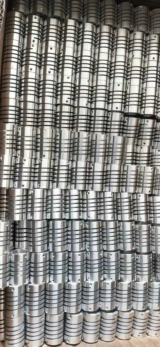
17-4 PH · Ø2.5 × 70 mm · 5,000 parts · turning + cross drilling · optical and gauge evidence.
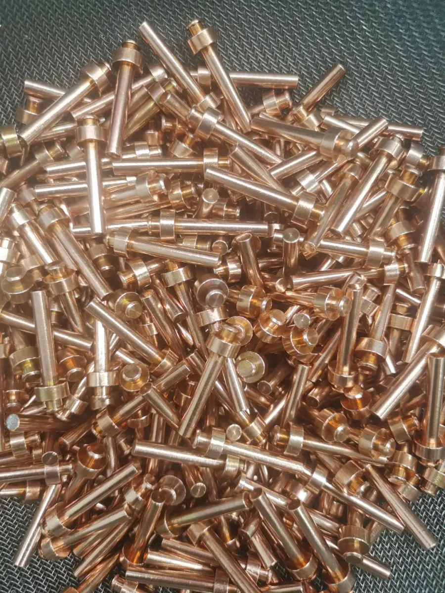
C360 brass · Ø8 × 24 mm · 20,000 parts · thread + cross-hole · gauge and batch inspection report.
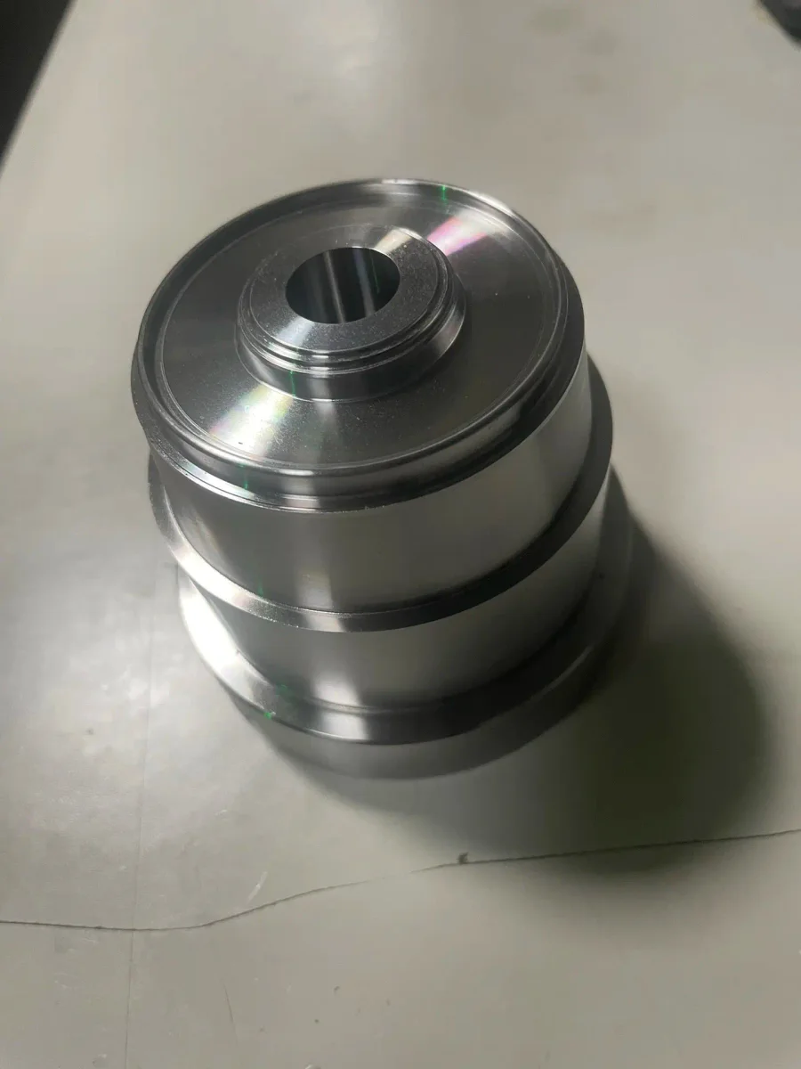
316 stainless · Ø1.8 × 12 mm · 2,500 parts · micro drilling + back working · traceability and optical inspection.
Upload the model, drawing and production context. Mockup will compare Swiss-type machining with conventional turning and confirm the route, cost drivers, tolerance strategy and inspection requirements.
Get my Swiss machining quote↗MODEL + DRAWING + ANNUAL DEMAND RECOMMENDEDSwiss machining is a turning process in which a sliding headstock feeds bar stock through a guide bushing. The material is supported close to the cutting tool, helping reduce deflection when machining small, slender and complex components.
Conventional lathes generally hold the workpiece in a fixed chuck with more unsupported material. A Swiss machine moves bar through a guide bushing near the cutting zone, which is often better for high length-to-diameter ratios and integrated small-part production.
Mockup publishes a Swiss machining range of Ø0.5–42 mm and practical lengths up to 600 mm. Final routing depends on the machine, guide bushing, stock, geometry, length-to-diameter ratio and inspection method.
It is especially efficient for repeat production, but complex prototypes and low-volume work can benefit when Swiss machining consolidates operations or controls difficult slender geometry. Mockup compares the total route during review.
Selected features can be reviewed down to ±0.002 mm. Diameter, length, runout, material, tool wear, temperature and measurement method determine the final commitment against the drawing.
Yes. Live tooling can produce cross-holes, flats, slots and axial or radial features. Capability depends on the selected machine configuration and design access.
Provide a 3D model, dimensioned drawing, material, quantity, annual demand, release schedule and target date. Identify critical diameters, threads, fits, finish, traceability and inspection-document requirements.
Upload the model, drawing, quantity and annual demand. We will compare Swiss-type machining with conventional turning and confirm the route, cost drivers, tolerance strategy and inspection requirements.